Brooks, Model 5850i – Brooks Instrument 5850i User Manual
Page 43
4-15
Brooks
®
Model 5850i
Section 4 Maintenance
Installation and Operation Manual
X-TMF-5850i-MFC-eng
Part Number: 541B108AAG
December, 2008
4-6 Use of Orifice Sizing Nomograph
The Orifice and Restrictor Sizes for 5850i should be sized using the
"Brooks Thermal Mass Flowmeter Sizing Selection Program" Revision 8.6
or later. A copy can be requested through your local Brooks Sales
Representive or through the Brooks Customer Service Department.
The Orifice Sizing Nomograph, Table 4-4, is used to calculate the control
valve's orifice size when changing any or all of the following factors from
the original factory calibration.
gas
operating pressure (inlet and outlet)
flow range
The flow controller's orifice is factory-sized to a preselected gas, operating
pressure and flow range. Note that the orifice is marked with its size in
thousandths of an inch. When changing the aforementioned factors,
calculate the new orifice size by following the procedure and example
outlined below.
Example: Determine the orifice size for the following conditions:
Gas: Hydrogen
Flow Rate: 2000 sccm
Outlet Pressure: 30 psig
Inlet Pressure: 50 psig
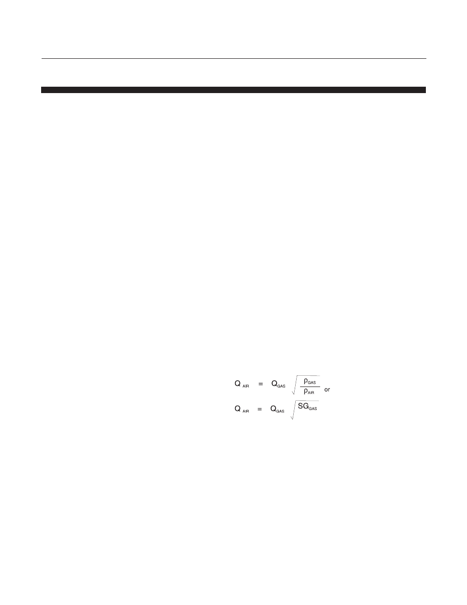
1. Determine air equivalent flow rate (refer to Table 4-3).
where SG
AIR
= 1.00
Q
Air
=
Air equivalent flow rate (sccm)
Q
gas
=
Desired flow rate of the gas (sccm)
(Based on 0°C Standard temperature)
D
Air
=
Density of Air at 70°F
D
gas
=
Density of the gas (taken at customer temperature)
SG
gas
=
Specific gravity of the gas (taken at customer
temperature)
Refer to Table 4-3 for specific gravities.