Brooks, Model 5850i – Brooks Instrument 5850i User Manual
Page 36
Brooks
®
Model 5850i
4-8
Section 4 Maintenance
Installation and Operation Manual
X-TMF-5850i-MFC-eng
Part Number: 541B108AAG
December, 2008
6. Remove and note the position of the valve spring spacers (10), which
may be located above and/or below the lower guide spring (8). Remove
the preload spacer spring (33)(NO Valve).
7. Unscrew the orifice (12) from the flow controller body(14).
8. Carefully unscrew the valve seat (11) from the plunger assembly (7)(NC
Valve) or the plunger assembly (31,32,35)(NO Valve).
Note the position and number of spacers (9) that are stacked on the
threaded end of the valve seat.
9. Remove the three screws (20) attaching the electronics cover. Remove
the electronics cover (23).
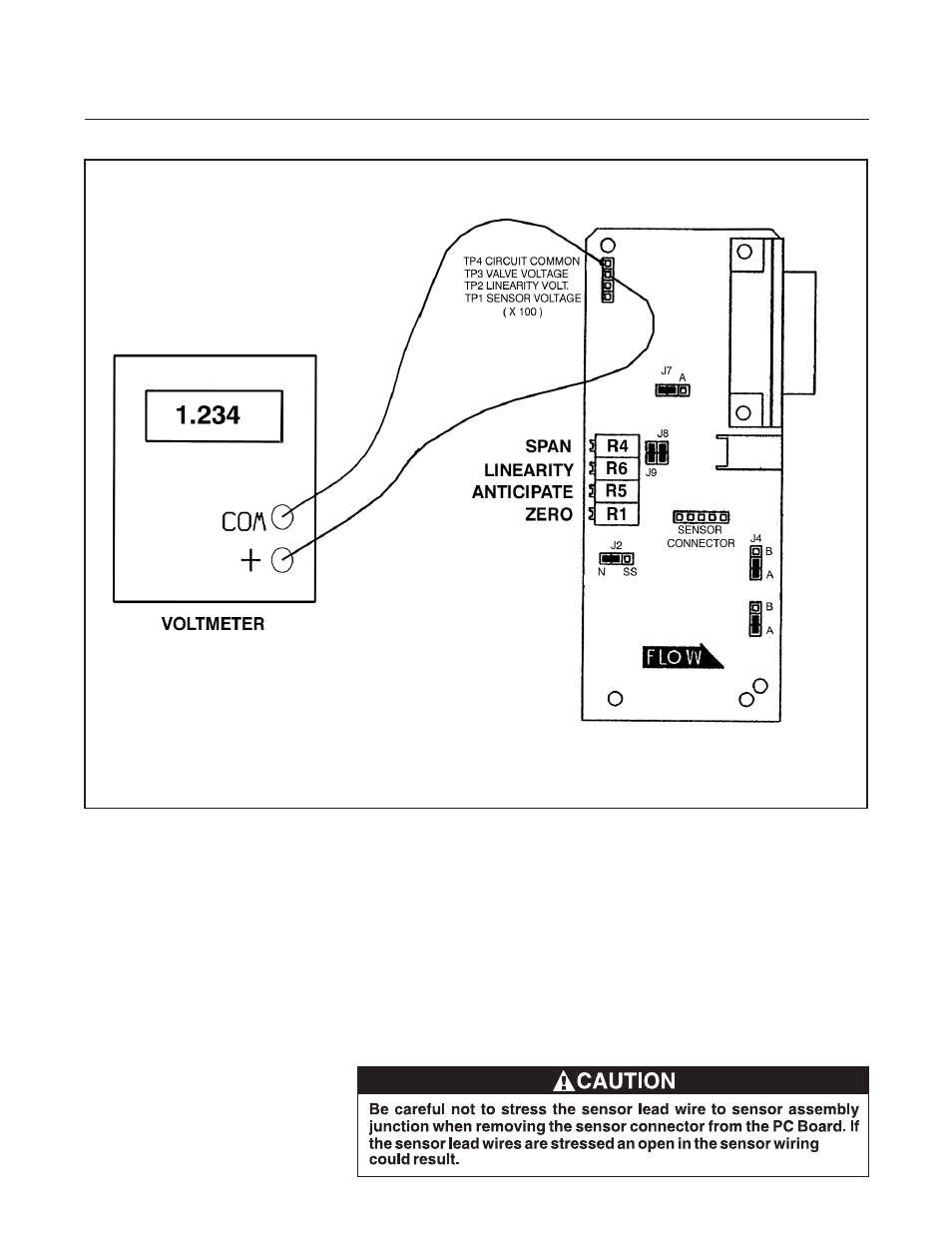
Figure 4-3 Voltmeter Connections for Valve Adjustment
See also other documents in the category Brooks Instrument Hardware:
- QMBC (52 pages)
- SolidSense II (28 pages)
- SLA7810/20 (36 pages)
- SLA5810/20 (50 pages)
- SLA5840 (46 pages)
- SLA7840 (40 pages)
- 5866E (65 pages)
- IPS122 2 Indicating Pressure Switches" (18 pages)
- IPT122 2 Indicating Pressure Transmitters" (22 pages)
- 8601 (20 pages)
- PTI Metal Seal Mass Flow Controller w/Real-Time Flow Error Detection & Advanced Diagnostics (82 pages)
- SLA5800 Series (76 pages)
- 5800S Series (50 pages)
- 4800 Series (50 pages)
- 5850EM (74 pages)
- 5851EM (62 pages)
- 5850E (64 pages)
- 5851E (64 pages)
- 5860E (46 pages)
- 5861E (44 pages)
- 5851i (62 pages)
- 5860i (48 pages)
- 5861i (48 pages)
- 5881/91 (40 pages)
- GF40 (78 pages)
- SLAMf Series (76 pages)
- Mfi Series (82 pages)
- 0254 (124 pages)
- 0260 (14 pages)
- CMC Series (36 pages)
- XacTorr CMX45 (64 pages)
- MT3809G (78 pages)
- MT3809E (72 pages)
- MT3810 (66 pages)
- 3600 Series (56 pages)
- 3750 (64 pages)
- Control Valve (16 pages)
- GT1000 (52 pages)
- 1100 Series (52 pages)
- 1307 (18 pages)
- 1358 (44 pages)
- 1350 (46 pages)
- 1250 (2 pages)
- FC8800 Series (48 pages)