Brooks, Model 5850i – Brooks Instrument 5850i User Manual
Page 13
2-3
Brooks
®
Model 5850i
Section 2 Installation
Installation and Operation Manual
X-TMF-5850i-MFC-eng
Part Number: 541B108AAG
December, 2008
2-5 Installation (Refer to Figures 2-1 through 2-4)
Recommended installation procedures:
a. The Model 5850i should be located in a clean dry atmosphere
relatively free from shock and vibration.
b. Leave sufficient room for access to the electrical components.
c. Install in such a manner that permits easy removal if the instrument
requires cleaning.
d. The Model 5850i Mass Flow Controller can be installed in any
position. However, mounting orientations other than the original
factory calibration (see data sheet) will result in a ±0.5% maximum
full scale shift after re-zeroing.
e. When installing controllers with full scale flow rates of 10 slpm or
greater, be aware that sharp abrupt angles in the system piping
directly upstream of the controller may cause a small shift in accu-
racy. If possible, have at least ten pipe diameters of straight tubing
upstream of the 5850i MFC.
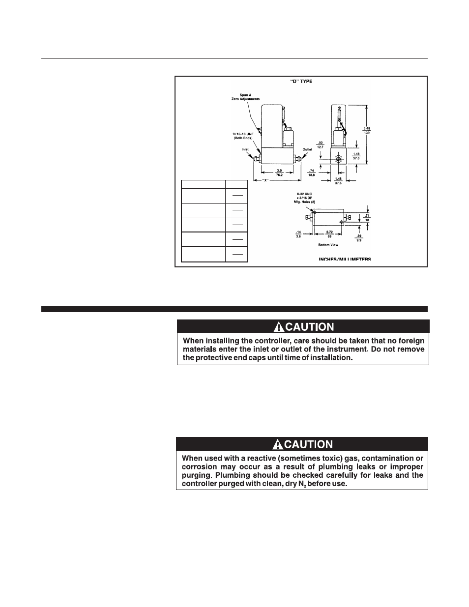
Figure 2-1 Model 5850
i Dimensions
Connection
"X" Dim.
1/8" Compression
4.84
Fitting
122.9
1/4" Compression
5.02
Fitting
127.5
1/4" Tube VCO
4.56
115.8
1/4" Tube VCR
4.88
124.0
3/8" Compression
5.14
Fitting
130.5