Brooks, Model 5850i – Brooks Instrument 5850i User Manual
Page 18
2-8
Brooks
®
Model 5850i
Section 2 Installation
Installation and Operation Manual
X-TMF-5850i-MFC-eng
Part Number: 541B108AAG
December, 2008
2-8 Configuring the PC Board
NOTE: To obtain access to the jumpers, the electronics cover can must be
removed. Disconnect the power to the mass flow controller and any cables
to the D-connector and the valve coil connector. Remove the three screws at
the base of the can and remove the top jack post of the D-connector.
Remove the can. The can must be replaced before returning the unit to
service. Refer to Section 2-6 for the proper electrical hook-up. Refer to Figure
3-5 for pc board jumper locations and functions.
Setpoint (Command) Input
The mass flow controller can be configured for voltage or current setpoint
(command) input. Jumper J7 (green) must be in the right-hand position for
0-5 Vdc setpoint and in the left-hand position for a 4-20 mAdc setpoint
input.
Signal Output
A 0-5 Vdc flow signal output is always available. The current signal output
is jumper selectable for either 0-20 mAdc or 4-20 mAdc. Jumpers J3 and
J4 (blue) must be in the upper position for 0-20 mAdc output and in the
lower position for 4-20 mAdc output.
NOTE: Both J3 and J4 must be in the same position. Jumpers J3 and J4
do not affect the voltage output.
Soft Start
To enable soft start, place Jumper J2 (red) in the right-hand position (SS).
To disable soft start, place jumper J2 in the left-hand position (N).
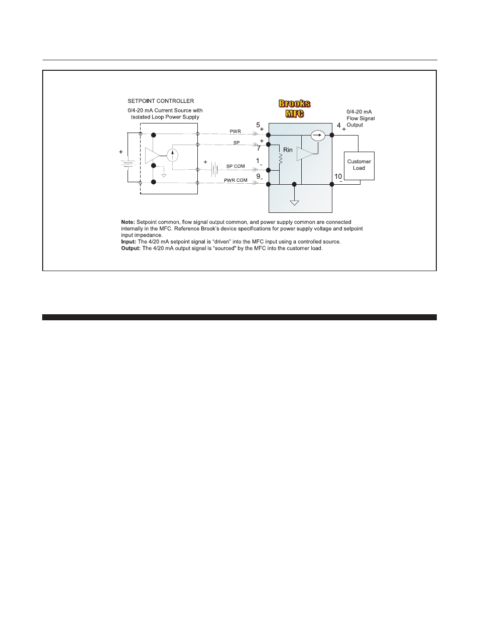
Figure 2-6 Recommended I/O Wiring Configuration for Current Signals (Isolated Power Supply)