Brooks, Model 5850i – Brooks Instrument 5850i User Manual
Page 16
2-6
Brooks
®
Model 5850i
Section 2 Installation
Installation and Operation Manual
X-TMF-5850i-MFC-eng
Part Number: 541B108AAG
December, 2008
Signal Output
The flow signal output can be measured as a voltage and a current
simultaneously on two different pins of the D-connector. Pin 2 indicates the
flowrate with a 0-5 Vdc signal proportional to the mass flow rate. Pin 4
indicates the flowrate with either a 0-20 mAdc or 4-20 mAdc current signal
as determined by jumpers on the pc board (refer to Section 2-7 for jumper
positions). Both the current and voltage signals are returned on pin 10 of
the D-connector.
(The Brook’s MFC acts as the current source when providing a 0/4-20 mA
output signal to the load. The output signal is “driven” by the MFC into the
customer load. Reference Brook’s device specifications for maximum load
capacity.)
Supply
The power for the mass flow controller is connected to pin 5 (+22.5 to +28
Vdc) and pin 9 (supply common) of the D-connector. Refer to Section 1-3
for the power requirements.
NOTE: The length of wire for the power supply connections (pins 5 & 9)
must be kept as short as possible to insure the minimum voltage (+15) is
available at the mass flow controller.
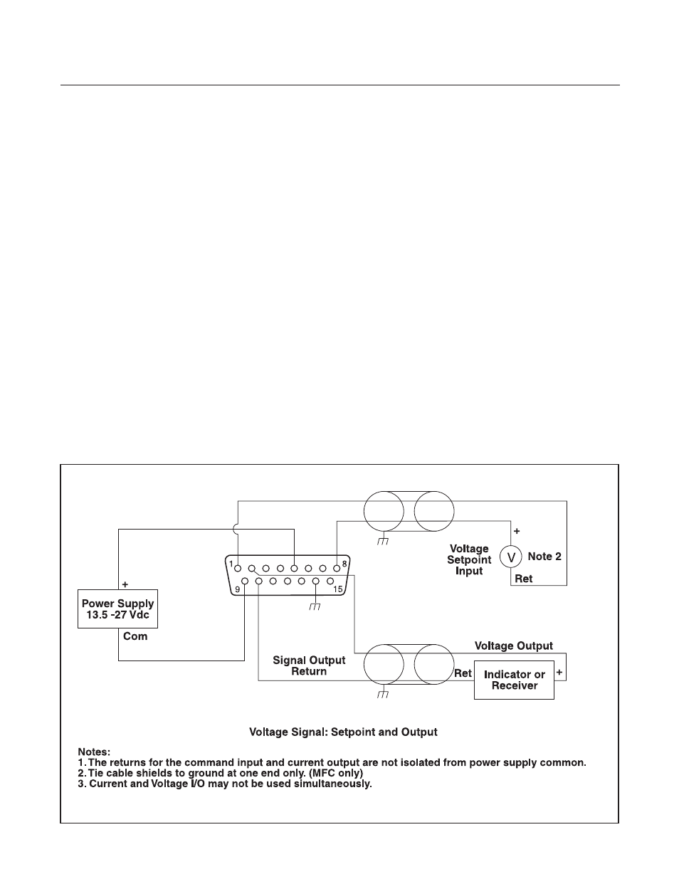
Figure 2-4 Common Electrical Hook-Ups, Voltage I/O version