Brooks, Model 5850i – Brooks Instrument 5850i User Manual
Page 23
3-5
Brooks
®
Model 5850i
Section 3 Operation
Installation and Operation Manual
X-TMF-5850i-MFC-eng
Part Number: 541B108AAG
December, 2008
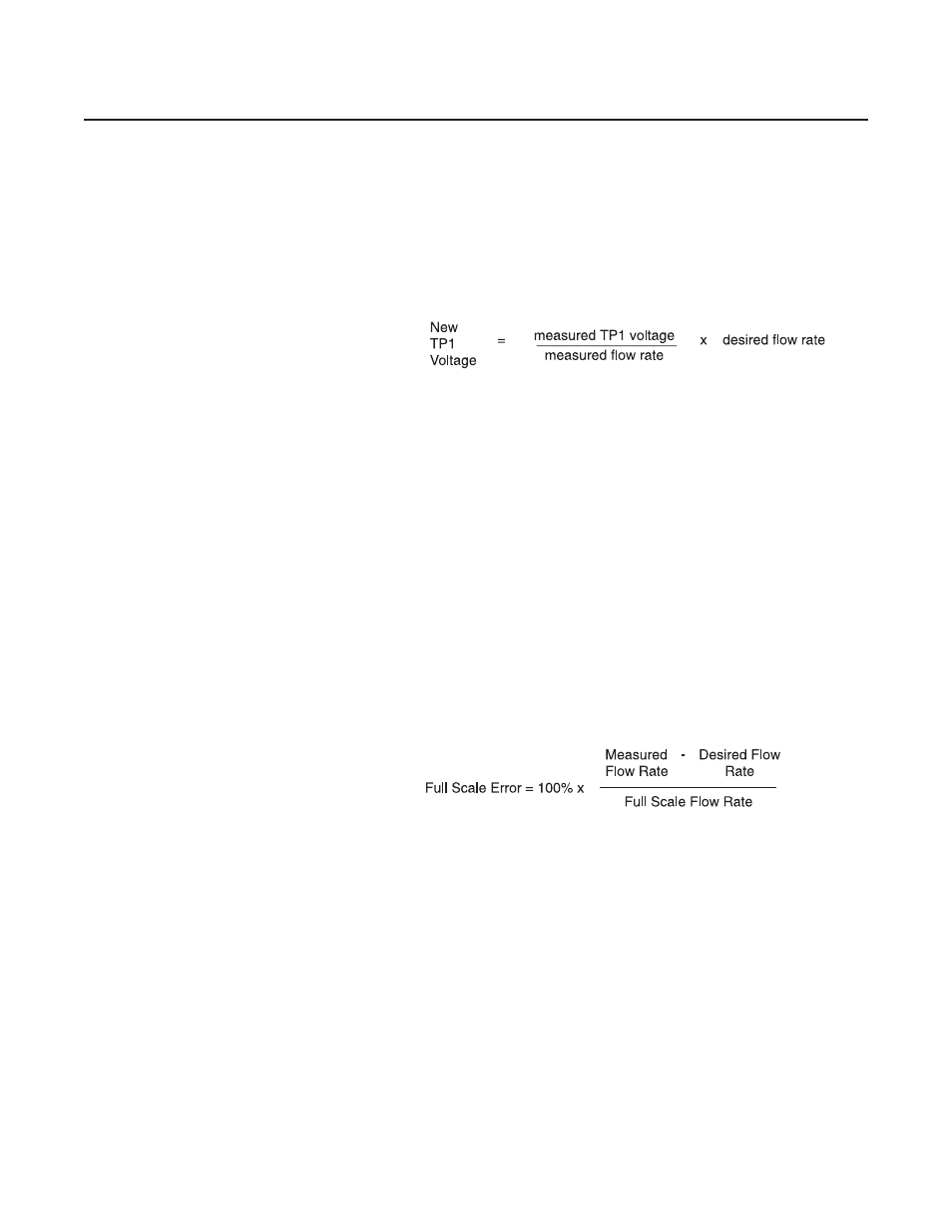
f. Connect the DVM positive lead to TP1 (100x sensor voltage) and
the negative lead to TP4 (circuit common). The setpoint should still
be set at 100% flow (5.000V). Measure the flow rate using suitable
volumetric calibration equipment. To adjust the controller to the
proper full scale flow, calculate a new TP1 voltage using the follow-
ing equation:
Adjust the span potentiometer until the voltage at TP1 is equal to the value
calculated above. Recheck the flow rate after the flow is stable (at least
two minutes). Repeat this check and adjustment procedure until the
measured flow rate is within 1% of the desired flow rate.
NOTE: The voltage at TP1 is 100 times the output voltage of the sensor. This
voltage can range from 1.2 to 12 volts, however, it is recommended that this
voltage stays between 2.0 and 9.0 volts for proper operation. If the
recommended voltage range exceeds that desired, accuracy and/or signal
stability may not be achieved. If one of the limits is reached, check the orifice
and restrictor sizing procedures. Refer to Sections 4-6 and 4-7 respectively.
g. Adjust the setpoint for 0 % flow. Connect the DVM positive lead to
0-5V signal output (Pin 2) and the negative lead to TP4. Readjust
the zero potentiometer for an output of 0 mV ±2 mV as necessary.
h. Adjust the setpoint for 50% flow and measure the flow rate. Calculate
the error as a percentage of full scale.
i. Calculate the TP2 correction voltage: (error recorded in step “h”) x
0.450 volts
Example:
Error = -1.5%
TP2 correction voltage
= -1.5 x 0.450
= -0.675 volts
New TP2 voltage
= 0 volts + (-0.675)
= -0.675 volts
j. Set the command potentiometer for 100% flow (5.000V). Connect the
DVM positive lead to TP2 and the negative lead to TP4.
k. Adjust the linearity potentiometer for an output equal to the new
calculated TP2 voltage.
l. Repeat steps f, g and h.
1. If the error recorded in step “h” is less than 0.5%, then the calibration
procedure is complete.