4 adjustment, Remove the transmission cover, 5 clutch adjustment table – FlexLink WL322 (322 мм) Монтаж User Manual
Page 37
Start-up and testing
C
rea
ted by
EBCCW
00:
06
33
5683EN-1
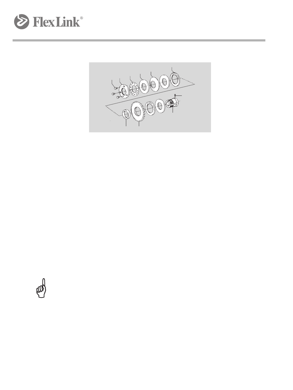
12.2.4
Adjustment
2
3
7
6
5
9
4
10
1
8
1.
Remove the transmission cover.
2.
Unscrew the three screws (8) so that the outer ring (7) can be rotated
freely.
3.
Hand-tighten the outer ring (7) to stop (no tools!).
4.
Look for the desired maximum traction force in the table to the right
and determine the X value for that force.
5.
Positive X-value: (If the X value is negative (X
≤0) ignore step 5 and go
to step 6.) Turn the outer ring (7) counter-clockwise the number of
divisions given by the table, i.e. the X value. One division is defined as
the angle (30°) between adjacent holes in the stop ring (6). Check that
screws (8) align with the holes in the stop ring (6).
6.
Negative X-value: (If the X value is positive (X
≥0) ignore step 6 and go
to step 7.) Turn the outer ring (7) clockwise with a hook wrench, the
number of divisions given by the table, i.e. the X value. One division is
defined as the angle (30°) between adjacent holes in the stop ring (6).
Check that screws (8) align with the holes in the stop ring (6).
7.
Tighten the three screws (8) to stop. Use 10 mm wrench
Important:
The slip clutch is not a personal safety device. It is primarily intended to protect the
equipment.
12.2.5
Clutch adjustment table
F
max
is the desired maximum traction force applied to the chain by the drive
unit. The clutch will start slipping at forces above F
max.
NB: Note