Q3 - electrical connections power connections, Transducer connections – Dynasonics TFXL Clamp-On Ultrasonic Flow User Manual
Page 6
6
06-TTM-UM-00158 8/2012
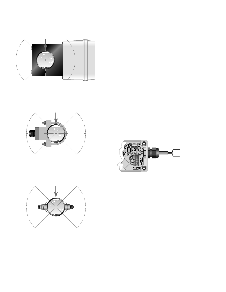
pipe, choose a fl ow meter mounting location within approxi-
mately 45-degrees of the side of the pipe. See Figure Q.2. Locate
the fl ow meter so that the pipe will be completely full of liquid
when fl ow is occurring in the pipe. Avoid mounting on vertical
pipes where the fl ow is moving in a downward direction.
3) Apply a single ½” (12 mm) bead of acoustic couplant grease
to the upstream transducer and secure it to the pipe with a
mounting strap.
4) Apply acoustic couplant grease to the downstream transducer
and press it onto the pipe using hand pressure at the lineal
distance calculated by the ULTRALINK software utility.
5) Space the transducers according to the recommended values
from the ULTRALINK software utility. Secure the transducers with
the mounting straps at these locations.
Q3 - ELECTRICAL CONNECTIONS
POWER CONNECTIONS
1) Power for the TFXL fl ow meter is obtained from a direct current
(DC) power source. The power source should be capable of
supplying between 11 and 28 VDC at a minimum of 250 milli-
amps. With the power from the DC power source disabled or
disconnected, connect the positive supply wire and ground to
the appropriate fi eld wiring terminals in the fl ow meter. See
Figure Q.3. A wiring diagram decal is located on the inner cover
of the fl ow meter enclosure for reference.
O
N
1
PIC16F628
DC Ground
11 - 28 VDC
DC Ground
11 - 28 VDC
FIGURE Q.3 - POWER CONNECTIONS
TRANSDUCER CONNECTIONS
(Remote Mount Transducers)
1) Guide the transducer terminations through the transmitter
conduit hole located in the bottom-left of the enclosure using
a sealed cord grip or NEMA 4 conduit connection. Secure the
transducer cable with the supplied conduit nut (if fl exible con-
duit was ordered with the transducer).
2) The remote mount transducers use an add-in connection board
on the left had side of the meter below the LCD (TFXL 2 version).
The terminals within TFXL are of a screw-down barrier terminal
type. Connect the appropriate wires at the corresponding screw
terminals in the transmitter. Observe upstream and downstream
orientation and wire polarity. See Figure Q.4.
45°
45°
YES
YES
45°
45°
FLOW METER
MOUNTING ORIENTATION
DTTS and DTTC TRANSDUCERS
TOP OF
PIPE
45°
45°
YES
YES
45°
45°
FLOW METER
MOUNTING ORIENTATION
DTTN and DTTH TRANSDUCERS
TOP OF
PIPE
45°
45°
YES
YES
45°
45°
FLOW METER
MOUNTING ORIENTATION
2” DTTS and DTTC TRANSDUCERS
TOP OF
PIPE
FIGURE Q.2 - TRANSDUCER ORIENTATION
(Integral mount shown)
(Remote mount shown)