Dynasonics TFXL Clamp-On Ultrasonic Flow User Manual
Page 20
20
06-TTM-UM-00158 8/2012
Frequency
Transducers
Transmission
Modes
Pipe Size
and Type
2 MHz
All ½” thru 1½”
Small Pipe and
Tube
2” Tubing
Selected by
Firmware
Specifi c to
Transducer
1 MHz
2” ANSI Pipe and
Copper Tube
Selected by
Firmware
Specifi c to
Transducer
Standard and
High Temp
W, V, and Z
2” and Greater
TABLE 4.1 - TRANSDUCER FREQUENCIES
Transducer Spacing is a value calculated by the TFXL
fi rmware that takes into account pipe, liquid, transducer
and mounting information. This spacing will adapt as these
parameters are modifi ed. The spacing is given in inches
for English units selection and millimeters for Metric. This
value is the lineal distance that must be between the trans-
ducer alignment marks. Selection of the proper transducer
mounting method is not entirely predictable and many times
is an iterative process.
NOTE: This setting only applies to DTTN, and DTTH
transducers.
Transducer Flow Direction allows the change of the
direction the meter assumes is forward. When mounting
TFXL meters with integral transducers, this feature allows
upstream and downstream transducers to be “electronically”
reversed, making upside down mounting of the display
unnecessary.
Pipe Material is selected from the pull-down list. If the pipe
material utilized is not found in the list, select Other and
enter the actual pipe material Sound Speed and Roughness
(much of this information is available at web sites such as
www.ondacorp.com/tecref_acoustictable.shtml
for pipe
relative roughness calculations.
Pipe O.D. and Wall Thickness are based on the physical
dimensions of the pipe on which the transducers will be
mounted. Enter this value in inches for English units or milli-
meters for Metric units.
NOTE: Charts listing popular pipe sizes have been included
in the
Appendix
of this manual. Correct entries for pipe O.D.
and pipe wall thickness are critical to obtaining accurate fl ow
measurement readings.
Liner Material is selected from the pull-down list. If the pipe
liner material utilized is not included in the list, select Other
and enter liner material Sound Speed and Roughness
(much of this information is available at web sites such as
www.ondacorp.com/tecref_acoustictable.shtml
. See
Page 40 for pipe liner relative roughness calculations.
Fluid Type is selected from a pull-down list. If the liquid is
not found in the list, select Other and enter the liquid Sound
Speed and Absolute Viscosity into the appropriate boxes.
The liquid’s Specifi c Gravity is required if mass measure-
ments are to be made.
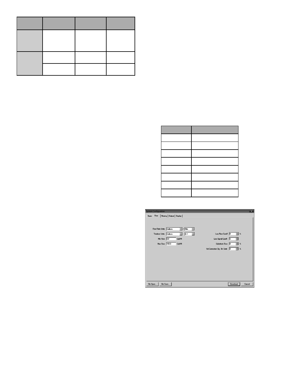
FLOW TAB
Flow Rate Units are selected from the drop-down lists.
Select an appropriate rate unit and time from the two lists.
This entry also includes the selection of Flow Rate Interval
after the / sign.
Totalizer Units are selected from drop-down lists. Select
an appropriate totalizer unit and totalizer exponent. The
totalizer exponents are in scientifi c notation and permit the
eight digit totalizer to accumulate very large values before
the totalizer “rolls over” and starts again at zero. Table 4.2
illustrates the scientifi c notation values and their respective
decimal equivalents.
Exponent
Display Multiplier
E-1
Ч 0.1 (ч10)
E0
× 1 (no multiplier)
E1
× 10
E2
× 100
E3
× 1,000
E4
× 10,000
E5
× 100,000
E6
× 1,000,000
TABLE 4.2 - EXPONENT VALUES
FIGURE 4.4 - FLOW TAB
Min Flow is the minimum volumetric fl ow rate setting
entered to establish fi ltering parameters. Volumetric entries
will be in the Flow Rate Units. For unidirectional measure-
ments, set Min Flow to zero. For bidirectional measurements,
set Min Flow to the highest negative (reverse) fl ow rate
expected in the piping system.
Max Flow is the maximum volumetric fl ow rate setting
entered to establish fi ltering parameters. Volumetric entries