Dynasonics TFXL Clamp-On Ultrasonic Flow User Manual
Page 22
22
06-TTM-UM-00158 8/2012
are examined by the Bad Data Rejection fi lter. The value is
entered as a percentage of actual fl ow rate.
For example, if the average fl ow rate is 100 GPM and the
Flow Filter Hysteresis is set to 5%, a fi lter window of 95-105
GPM is established. Successive fl ow measurements that are
measured within that window are recorded and averaged in
accordance with the Flow Filter Damping setting. Flow read-
ings outside of the window are held up in accordance with
the Bad Data Rejection fi lter.
Flow Filter MinHysteresis sets a minimum hysteresis
window that is invoked at sub 0.25 FPS (0.08 MPS) fl ow rates,
where the “of rate” Flow Filter Hysteresis is very small and
ineff ective. This value is entered in pico-seconds (ρ sec) and
is diff erential time. If very small fl uid velocities are to be
measured, increasing the Flow Filter MinHysteresis value
can increase reading stability.
Flow Filter Sensitivity allows confi guration of how fast the
Flow Filter Damping will adapt in the positive direction.
Increasing this value allows greater damping to occur faster
than lower values. Adaptation in the negative direction is not
user adjustable.
Bad Data Rejection is a value related to the number of
successive readings that must be measured outside of
the Flow Filter Hysteresis or Flow Filter MinHysteresis
windows before the fl ow meter will use that fl ow value.
Larger values are entered into Bad Data Rejection when
measuring liquids that contain gas bubbles, as the gas
bubbles tend to disturb the ultrasonic signals and cause
more extraneous fl ow readings to occur. Larger Bad Data
Rejection values tend to make the fl ow meter more sluggish
to rapid changes in actual fl ow rate.
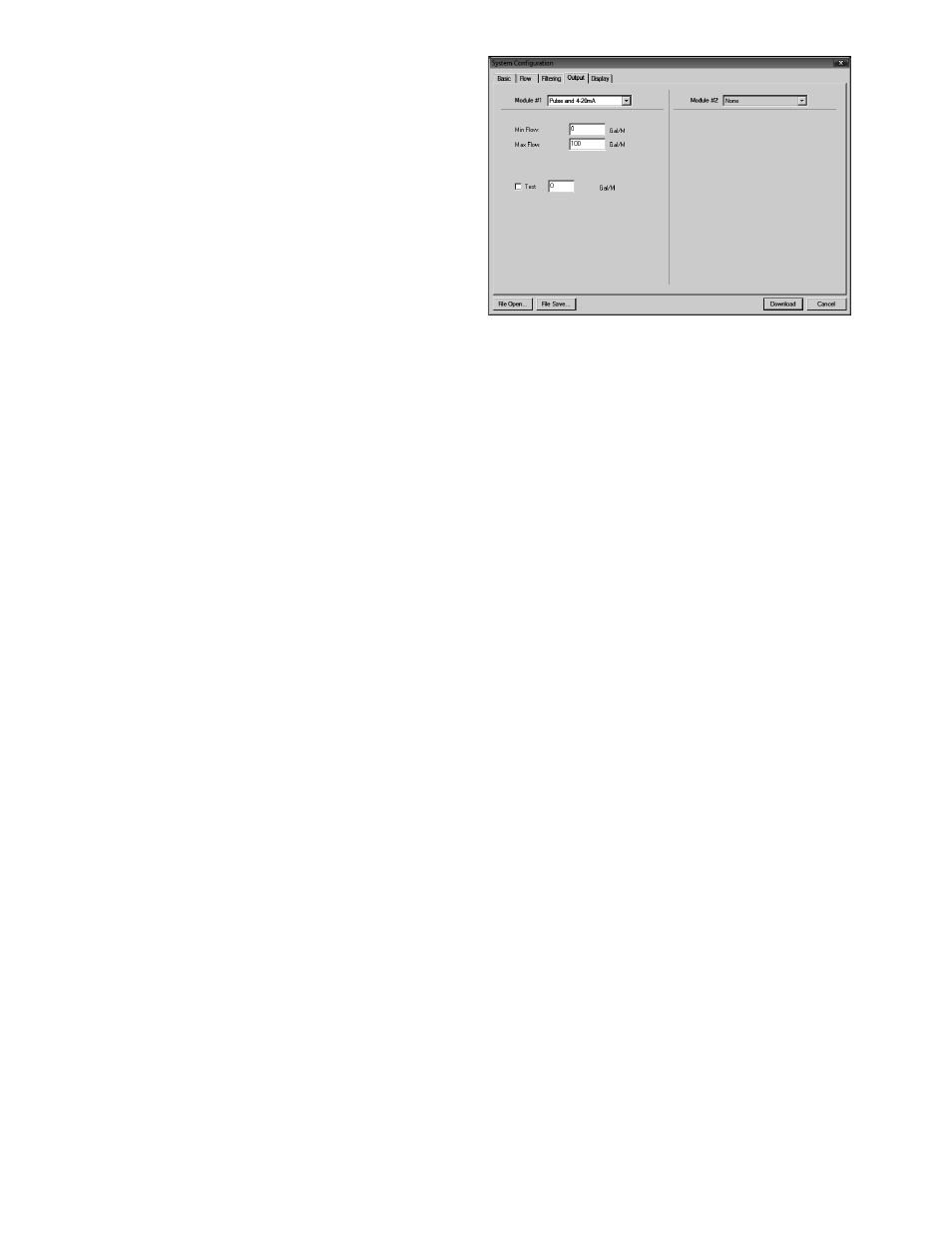
OUTPUT TAB
The entries made in the Output tab establish input and
output parameters for the fl ow meter. Select the appropriate
function from the pull-down menu and press the Down-
load button. When a function is changed from the factory
setting, a Confi guration error (1002) will result. This error
will be cleared by resetting the TFXL microprocessor from
the Communications/Commands/Reset Target button or
by cycling power on the TFXL fl ow meter. Once the proper
output is selected and the microprocessor is reset, calibration
and confi guration of the modules can be completed.
FIGURE 4.6 - OUTPUT TAB
CHANNEL 1 - 4-20 mA FREQUENCY
CONFIGURATION
NOTE: The 4-20 mA Output Frequency Menu applies to all
TFXL versions and is the only output choice for Channel 1.
The Channel 1 menu controls how the 4-20 mA output is
spanned for all TFXL models.
The Flow at 4 mA / 0 Hz and Flow at 20 mA / 1,000 Hz settings
are used to set the span for both the 4-20 mA output and the
0-1,000 Hz frequency output on the TFXL meter versions.
The 4-20 mA output is internally powered (current sourcing)
and can span negative to positive fl ow rates. This output
interfaces with virtually all recording and logging systems
by transmitting an analog current that is proportional to
system fl ow rate. Independent 4 mA and 20 mA span settings
are established in fi rmware using the fl ow measuring range
entries. These entries can be set anywhere in the - 40 to + 40
FPS (-12 to +12 MPS) range of the instrument. Resolution of
the output is 12-bits (4096 discrete points) and can drive up
to a 900 Ohm load. When powered by a DC supply, the load is
limited by the input voltage supplied to the instrument. See
Figure 3.1 for allowable loop loads.
Flow at 4 mA / 0 Hz
Flow at 20 mA / 1,000 Hz
The Flow at 4 mA / 0 Hz and Flow at 20 mA / 1,000 Hz entries
are used to set the span of the 4-20 mA analog output and
the frequency output on TFXL versions. These entries are
volumetric rate units that are equal to the volumetric units
confi gured as rate units and rate interval discussed on
Page 23.
For example, to span the 4-20 mA output from -100 GPM to
+100 GPM with 12 mA being 0 GPM, set the Flow at 4 mA / 0
Hz and Flow at 20 mA / 1,000 Hz inputs as follows: