Part 4 - ultralink utility, Introduction, System requirements – Dynasonics TFXL Clamp-On Ultrasonic Flow User Manual
Page 18: Installation
18
06-TTM-UM-00158 8/2012
For the TFXL this relationship is described by the following
equation. The 60,000 relates to measurement units in
volume/min. Measurement units in seconds, hours or days
would require a diff erent numerator.
60,000
K
factor
Full Scale Units
EQUATION 3.1 - K-FACTOR CALCULATION
A practical example would be if the MAX RATE for the appli-
cation were 400 GPM, the K-factor (representing the number
of pulses accumulated needed to equal 1 Gallon) would be:
60,000
150
400
K
factor
Pulses Per Gallon
GPM
If the frequency output is to be used as a totalizing output,
the TFXL and the receiving instrument must have identical
K-factor values programmed into them to ensure that accu-
rate readings are being recorded by the receiving instrument.
Unlike standard mechanical fl ow meters such as turbines,
gear or nutating disk meters, the K-factor can be changed by
modifying the MAX RATE fl ow rate value.
NOTE: For a full treatment of K-factors please see the
Appendix
of this manual.
There are two frequency output types available:
Turbine meter simulation - This option is utilized
when a receiving instrument is capable of interfacing
directly with a turbine fl ow meter’s magnetic pickup.
The output is a relatively low voltage AC signal whose
amplitude swings above and below the signal ground
reference. The minimum AC amplitude is approximately
500 mV peak-to-peak. To activate the turbine output
circuit, turn SW1 OFF.
0
500 mV
p-p
FIGURE 3.5 - FREQUENCY OUTPUT WAVEFORM
(SIMULATED TURBINE)
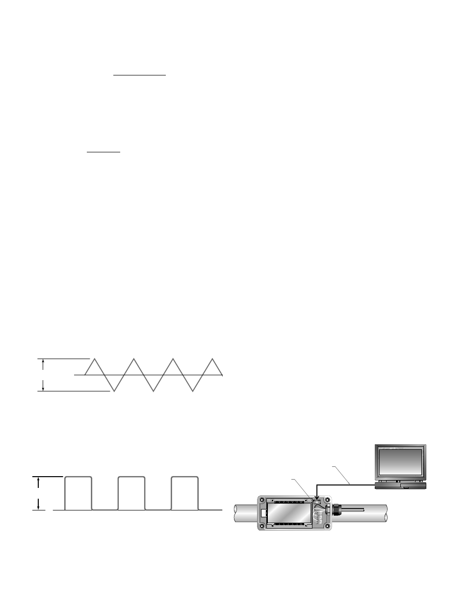
Square-wave frequency - This option is utilized when
a receiving instrument requires that the pulse voltage
level be either of a higher potential and/or referenced
to DC ground. The output is a TTL square-wave (5V).
0
5V
FIGURE 3.6 - FREQUENCY OUTPUT WAVEFORM
(SQUARE WAVE)
PART 4 - ULTRALINK UTILITY
INTRODUCTION
The ULTRALINK utility is used for confi guring, calibrating
and communicating with the TFXL family of fl ow meters.
Additionally, it has numerous troubleshooting tools to make
diagnosing and correcting installation problems easier.
This software has been designed to provide the TFXL user
with a powerful and convenient way to confi gure calibrate
and troubleshoot all TFXL family fl ow meters.
SYSTEM REQUIREMENTS
ULTRALINK requires a PC-type computer, running Windows
98, Windows ME, Windows 2000, Windows NT, Windows XP,
Windows Vista® or Windows® 7 operating systems and an
RS-232 9-pin communications port. (Part # D010-0204-001)
INSTALLATION
1) From the Windows “Start” button, choose the Run
command. From the “Run” dialog box, use the Browse
button to navigate to the ULTRALINK_Setup.exe fi le and
double-click.
2) The ULTRALINK Setup will automatically extract and
install on the hard disk. The ULTRALINK icon can then be
copied to the desktop, if desired.
NOTE: If a previous version of this software is installed, it
must be un-installed before a new version of the software
can be installed. Newer versions will “ask” to remove the old
version and perform the task automatically. Older versions
must be removed using the Microsoft Windows® Add/Remove
Programs applet.
NOTE: Most PCs will require a restart after a successful
installation.
INITIALIZATION
1) Connect the 9-pin serial end to an available port on the
PC. Connect the other end to the TFXL.
10 D
FLOW METER MOUNTING ORIENTATION
PC INTERFACE
CABLE
ULTRALINK
TM
PC INTERFACE
CABLE
PC INTERFACE
FIGURE 4.1 - PC CONNECTIONS
NOTE: It is advisable to have the TFXL meter powered up prior
to running this software.