Figure 2.7 - data display screen, Figure 2.8 - calibration page 3 of 3, Figure 2.9 - calibration points editor – Dynasonics TFXL Clamp-On Ultrasonic Flow User Manual
Page 14
14
06-TTM-UM-00158 8/2012
NOTE: Mounting of high temperature transducers is similar to
mounting the DTTN transducers. High temperature installa-
tions require acoustic couplant that is rated not to “fl ow” at
the temperature that will be present on the pipe surface.
DTTS/DTTC SMALL PIPE TRANSDUCER AND
INTEGRAL MOUNT INSTALLATION
The small pipe transducers are designed for specifi c pipe
outside diameters. Do not attempt to mount a DTTS/DTTC or
integral mount transducer onto a pipe that is either too large
or too small for the transducer. Contact the manufacturer to
arrange for a replacement transducer that is the correct size.
DTTS/DTTC and integral installation consists of the
following steps:
1) Apply a thin coating of acoustic coupling grease to both
halves of the transducer housing where the housing
will contact the pipe. See Figure 2.6.
2) On horizontal pipes, mount the transducer in an orien-
tation such that the cable exits at ±45 degrees from the
side of the pipe. Do not mount with the cable exiting on
either the top or bottom of the pipe. On vertical pipes
the orientation does not matter. See Figure 2.2.
3) Tighten the wing nuts or “U” bolts so that the acoustic
coupling grease begins to fl ow out from the edges of
the transducer or from the gap between the transducer
halves. Do not over tighten.
4) If signal strength is less than 5, remount the transducer
at another location on the piping system.
1⁄16” (1.5 mm)
Acoustic Couplant
Grease
FIGURE 2.6 - APPLICATION OF ACOUSTIC COUPLANT —
DTTS/DTTC AND INTEGRAL TRANSDUCERS
NOTE: If a DTTS/DTTC small pipe transducer was purchased
separately from the TFXL meter, the following confi guration
procedure is required.
DTTS/DTTC Small Pipe Transducer Confi guration
Procedure
1) Establish communications with the transit time meter.
See Part 4 - Software Utility.
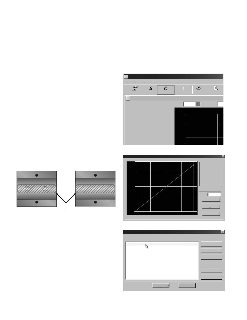
2) From the Tool Bar select Calibration. See Figure 2.7.
3) On the pop-up screen, click Next button twice to get to
Page 3 of 3. See Figure 2.8.
4) Click Edit.
5) If calibration point is displayed in Calibration Points Edi-
tor screen, record the information, highlight and click
Remove. See Figure 2.9.
6) Click ADD...
7) Enter Delta T, Un-calibrated Flow, and Calibrated Flow
values from the DTTS/DTTC calibration label, the click
OK. See Figure 2.10.
8) Click OK in the Edit Calibration Points screen.
9) Process will return to Page 3 of 3. Click Finish. See
Figure 2.8.
10) After “Writing Confi guration File” is complete, turn
power off . Turn on again to activate new settings.
UltraLINK Device Addr 127
Device Addr 127
Flow:
Totalizer Net:
Pos:
Neg:
Sig. Strength:
Margin:
Delta T:
Last Update:
Help
Window
Communications
View
Edit
File
Print Previe
1350 Gal/Min
0 OB
15.6%
100%
-2.50 ns
09:53:39
0 OB
0 OB
Errors
rro
!
Configuration
Calibration
Strategy
1600
2000
1200
Scale:
60 Min
Time:
200
U
U
FIGURE 2.7 - DATA DISPLAY SCREEN
Calibration (Page 3 of 3) - Linearization
Gal/M
Delta Time
1) Please establish a
reference flow rate.
1FPS / 0.3MPS Minimum.
2) Enter the reference flow
rate below. (Do not enter 0)
3) Wait for flow to stabilize.
4) Press the Set button.
Flow:
Set
Export...
Edit
28.2
FIGURE 2.8 - CALIBRATION PAGE 3 OF 3
Calibration Points Editor
Select point(s) to edit or remove:
Add...
Remove
Select All
Select All
Select None
Select None
Edit...
Cancel
OK
30.00 ns 2000.00 Gal/Min 1.000
30.00 ns 2000.00 Gal/Min 1.000
FIGURE 2.9 - CALIBRATION POINTS EDITOR