Part 3 - inputs/outputs, Top view of pipe – Dynasonics TFXL Clamp-On Ultrasonic Flow User Manual
Page 16
16
06-TTM-UM-00158 8/2012
calculated transducer spacing. See Figure 2.13. Using
fi rm hand pressure, slowly move the transducer both
towards and away from the upstream transducer while
observing signal strength. Clamp the transducer at the
position where the highest signal strength is observed.
Signal strength of between 5 and 98 is acceptable. The
factory default signal strength setting is 5, however
there are many application specifi c conditions that may
prevent the signal strength from attaining this level.
A minimum signal strength of 5 is acceptable as long as
this signal level is maintained under all fl ow conditions.
On certain pipes, a slight twist to the transducer may
cause signal strength to rise to acceptable levels.
8) Certain pipe and liquid characteristics may cause signal
strength to rise to greater than 98. The problem with
oper
ating a TFXL with very high signal strength is
that the signals may saturate the input amplifi ers
and cause erratic readings. Strategies for lowering
signal strength would be changing the transducer
mounting method to the next longest transmis-
sion path. For example, if there is excessive signal
strength and the transducers are mounted in a
Z-Mount, try changing to V-Mount or W-Mount.
Finally you can also move one transducer slightly
off line with the other transducer to lower signal
strength.
9)
Secure the transducer with a stainless steel strap
or other fastener.
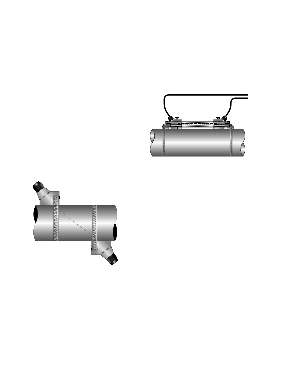
TOP VIEW
OF PIPE
FIGURE 2.13 - Z-MOUNT TRANSDUCER PLACEMENT
MOUNTING TRACK INSTALLATION
1) A convenient transducer mounting track can be used
for pipes that have outside diameters between 2 and
10 inches (50 and 250 mm). If the pipe is outside of that
range, select a V-Mount or Z-Mount mounting method.
2) Install the single mounting rail on the side of the pipe
with the stainless steel bands provided. Do not mount it
on the top or bottom of the pipe. Orientation on
vertical pipe is not critical. Ensure that the track is
parallel to the pipe and that all four mounting feet are
touching the pipe.
3) Slide the two transducer clamp brackets towards the
center mark on the mounting rail.
4) Place a single bead of couplant, approximately ½ inch
(12 mm) thick, on the fl at face of the transducer. See
Figure 2.4.
5) Place the fi rst transducer in between the mounting rails
near the zero point on the scale. Slide the clamp over
the transducer. Adjust the clamp/transducer such that
the notch in the clamp aligns with zero on the scale. See
Figure 2.14.
Top View
of Pipe
FIGURE 2.14 - MOUNTING TRACK INSTALLATION
6) Secure with the thumb screw. Ensure that the screw
rests in the counter bore on the top of the transducer.
(Excessive pressure is not required. Apply just enough
pressure so that the couplant fi lls the gap between the
pipe and transducer.)
7) Place the second transducer in between the mounting
rails near the dimension derived in the transducer
spacing section. Read the dimension on the mounting
rail scale. Slide the transducer clamp over the trans-
ducer and secure with the thumb screw.
PART 3 - INPUTS/OUTPUTS
GENERAL
The TFXL is available in two general confi gurations. There is
the standard TFXL fl ow model that is equipped with a 4-20
mA output and a rate frequency output.
The TFXL is also available with a totalizing pulse output.
4-20 mA OUTPUT
The 4-20 mA output interfaces with most recording and
logging systems by transmitting an analog current signal
that is proportional to system fl ow rate. The 4-20 mA output
is internally powered (current sourcing) and can span nega-
tive to positive fl ow/energy rates.