Quick-start operating instructions, W-mount v-mount z-mount – Dynasonics TFXL Clamp-On Ultrasonic Flow User Manual
Page 5
06-TTM-UM-00158 8/2012
5
QUICK-START OPERATING
INSTRUCTIONS
This manual contains detailed operating instructions for all
aspects of the TFXL instrument. The following condensed
instructions are provided to assist the operator in getting the
instrument started up and running as quickly as possible.
This pertains to basic operation only. If specifi c instrument
features are to be used or if the installer is unfamiliar with this
type of instrument, refer to the appropriate section in the
manual for complete details.
NOTE: The following steps require information supplied by
the TFXL meter itself so it will be necessary to supply power
to the unit, at least temporarily, and connect to a computer
using ULTRALINK to obtain setup information.
Q1 - TRANSDUCER LOCATION
1) In general, select a mounting location on the piping
system with a minimum of 10 pipe diameters (10 × the
pipe inside diameter) of straight pipe upstream and 5
straight diameters downstream. See Table 2.1 for addi-
tional confi gurations.
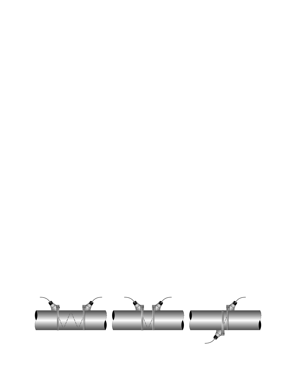
2) If the application requires DTTN or DTTH transducers
select a mounting method for the transducers based on
pipe size and liquid characteristics. See Table 2.2. Trans-
ducer confi gurations are illustrated in Figure Q.1 below.
NOTE: All DTTS and DTTC transducers use V-Mount
confi guration.
3) Enter the following data into the TFXL transmitter via
the ULTRALINK™ software utility:
1.
Transducer mounting method
2.
Pipe O.D. (Outside Diameter)
3.
Pipe wall thickness
4. Pipe
material
5.
Pipe sound speed*
6.
Pipe relative roughness*
7.
Pipe liner thickness
8.
Pipe liner material
9. Fluid
type
10.
Fluid sound speed*
11. Fluid
viscosity*
12. Fluid
specifi c gravity*
* NOMINAL VALUES FOR THESE PARAMETERS ARE
INCLUDED WITHIN THE TFXL OPERATING SYSTEM. THE
NOMINAL VALUES MAY BE USED AS THEY APPEAR OR
MAY BE MODIFIED IF THE EXACT SYSTEM VALUES ARE
KNOWN.
4) Record the value calculated and displayed as Trans-
ducer Spacing.
Q2 - PIPE PREPARATION AND TRANSDUCER
MOUNTING
(INTEGRAL & REMOTE DTTS AND DTTC
TRANSDUCERS)
1) Refer to the signal strength values available on the Data
Display screen in the ULTRALINK software utility.
2) The pipe surface, where the transducers are to be
mounted, must be clean and dry. Remove scale, rust or
loose paint to ensure satisfactory acoustic conduction.
Wire brushing the rough surfaces of pipes to smooth
bare metal may also be useful. Plastic pipes do not
require preparation other than cleaning.
On horizontal pipe, choose a fl ow meter mounting
location within approximately 45-degrees of the side of
the pipe. See Figure Q.2. Locate the fl ow meter so that
the pipe will be completely full of liquid when fl ow is
occurring in the pipe. Avoid mounting on vertical pipes
where the fl ow is moving in a downward direction.
3) Apply a single ½” (12 mm) bead of acoustic couplant
grease to the top half of the transducer and secure it to
the pipe with bottom half or U-bolts.
4) Tighten the nuts so that the acoustic coupling grease
begins to fl ow out from the edges of the transducer
and from the gap between the transducer and the pipe.
Finger tighten only. Do not over tighten.
(DTTN AND DTTH TRANSDUCERS)
1) Place the fl ow meter in signal strength measuring
mode. This value is available in the data display of the
software utility.
2) The pipe surface, where the transducers are to be
mounted, must be clean and dry. Remove scale, rust or
loose paint to ensure satisfactory acoustic conduction.
Wire brushing the rough surfaces of pipes to smooth
bare metal may also be useful. Plastic pipes do not
require preparation other than cleaning. On horizontal
TOP VIEW
OF PIPE
W-Mount
V-Mount
Z-Mount
TOP VIEW
OF PIPE
TOP VIEW
OF PIPE
FIGURE Q.1 - TRANSDUCER MOUNTING CONFIGURATIONS