Alignment marks, Transducer positioning, 12 mm) – Dynasonics TFXL Clamp-On Ultrasonic Flow User Manual
Page 13: Figure 2.3 - transducer alignment marks, Figure 2.4 - application of couplant
06-TTM-UM-00158 8/2012
13
the transducers should be mounted 180 radial degrees from
one another and at least 45 degrees from the top-dead-
center and bottom-dead-center of the pipe. See Figure 2.2.
Also see
Z-Mount Transducer Installation
. On vertical pipes
the orientation is not critical.
45°
45°
YES
YES
45°
45°
FLOW METER
MOUNTING ORIENTATION
DTTS and DTTC TRANSDUCERS
TOP OF
PIPE
45°
45°
YES
YES
45°
45°
FLOW METER
MOUNTING ORIENTATION
DTTN and DTTH TRANSDUCERS
TOP OF
PIPE
45°
45°
YES
YES
45°
45°
FLOW METER
MOUNTING ORIENTATION
2” DTTS and DTTC TRANSDUCERS
TOP OF
PIPE
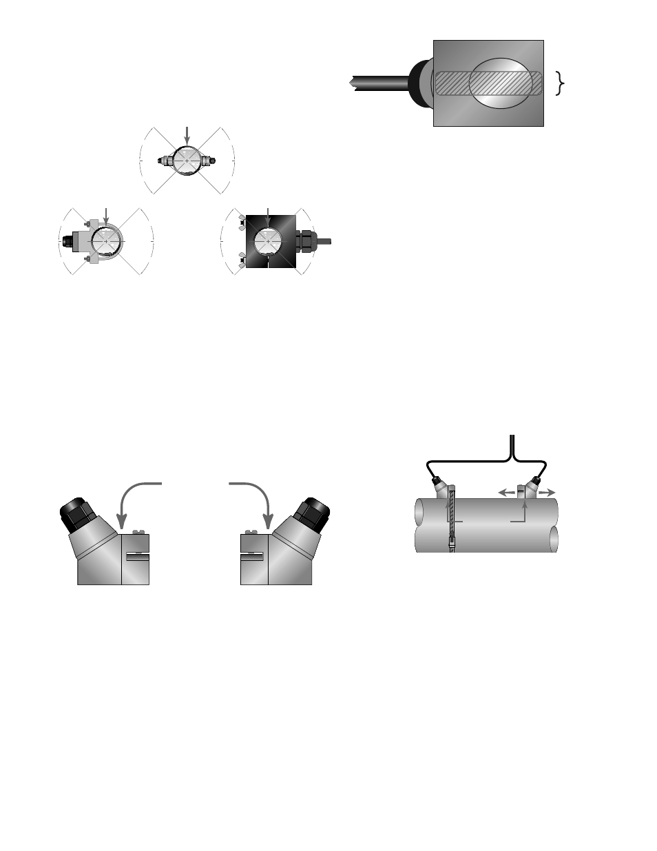
FIGURE 2.2 - TRANSDUCER ORIENTATION —
HORIZONTAL PIPES
The spacing between the transducers is measured between
the two spacing marks on the sides of the transducers. These
marks are approximately 0.75” (19 mm) back from the nose of
the DTTN and DTTH transducers. See Figure 2.3.
DTTS and DTTC transducers should be mounted with the
cable exiting within ±45 degrees of the side of a horizontal
pipe. See Figure 2.2. On vertical pipes the orientation does
not apply.
Alignment
Marks
FIGURE 2.3 - TRANSDUCER ALIGNMENT MARKS
V-MOUNT AND W-MOUNT INSTALLATION
APPLICATION OF COUPLANT
For DTTN and DTTH transducers, place a single bead of
couplant, approximately ½ inch (12 mm) thick, on the fl at
face of the transducer. See Figure 2.4. Generally, a silicone-
based grease is used as an acoustic couplant, but any grease-
like substance that is rated not to “fl ow” at the temperature
that the pipe may operate at will be acceptable. For pipe
surface temperature over 150° F (65° C), acoustic couplant
(P.N. D002-2011-011) is recommended.
½”
(12 mm)
FIGURE 2.4 - APPLICATION OF COUPLANT
TRANSDUCER POSITIONING
1) Place the upstream transducer in position and secure
with a mounting strap. Straps should be placed in the
arched groove on the end of the transducer. A screw
is provided to help hold the transducer onto the strap.
Verify that the transducer is true to the pipe and adjust
as necessary. Tighten the transducer strap securely.
2) Place the downstream transducer on the pipe at the
calculated transducer spacing. See Figure 2.5. Apply
fi rm hand pressure. If signal strength is greater than
5, secure the transducer at this location. If the signal
strength is not 5 or greater, using fi rm hand pressure
slowly move the transducer both towards and away
from the upstream transducer while observing signal
strength.
NOTE: Signal strength readings update only every few
seconds, so it is advisable to move the transducer 1⁄8”, wait, see
if signal is increasing or decreasing and then repeat until the
highest level is achieved.
Transducer
Spacing
FIGURE 2.5 - TRANSDUCER POSITIONING
Signal strength is displayed on the main data screen in
the software utility. See Part 4 of this manual for details
regarding the software utility. Clamp the transducer
at the position where the highest signal strength is
observed. The factory default signal strength cutoff
setting is 5, however there are many application specifi c
conditions that may prevent the signal strength from
attaining this level. For the TFXL, signal levels much
less than 5 will probably not be acceptable for reliable
readings.
3) If after adjustment of the transducers the signal
strength does not rise to above 5, then an alternate
transducer mounting method should be selected. If the
mounting method was W-Mount, then re-confi gure the
transmitter for V-Mount, move the downstream trans-
ducer to the new spacing distance and repeat Step 4.