Mounting transducers in z-mount configuration – Dynasonics TFXL Clamp-On Ultrasonic Flow User Manual
Page 15
06-TTM-UM-00158 8/2012
15
Model: DTTSJP-050-N000-N
S/N: 39647
Delta-T: 391.53nS
Uncal. Flow: 81.682 GPM
Cal. Flow: 80 GPM
391.53
81.682
80.000
Delta T:
Uncalibrated Flow:
Calibrated Flow:
ns
Gal/Min.
Gal/Min.
Cancel
OK
Edit Calibration Points
FIGURE 2.10 - EDIT CALIBRATION POINTS
MOUNTING TRANSDUCERS IN Z-MOUNT
CONFIGURATION
Installation on larger pipes requires careful measurements
of the linear and radial placement of the DTTN and DTTH
transducers. Failure to properly orient and place the trans-
ducers on the pipe may lead to weak signal strength and/or
inaccurate readings. This section details a method for prop-
erly locating the transducers on larger pipes. This method
requires a roll of paper such as freezer paper or wrapping
paper, masking tape and a marking device.
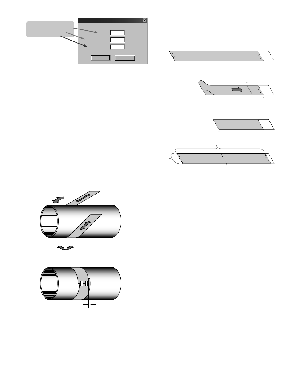
1) Wrap the paper around the pipe in the manner shown
in Figure 2.11. Align the paper ends to within ¼ inch
(6 mm).
2) Mark the intersection of the two ends of the paper to
indicate the circumference. Remove the template and
spread it out on a fl at surface. Fold the template in half,
bisecting the circumference. See Figure 2.12.
LESS THAN ¼” (6 mm)
FIGURE 2.11 - PAPER TEMPLATE ALIGNMENT
3) Crease the paper at the fold line. Mark the crease. Place
a mark on the pipe where one of the transducers will
be located. See Figure 2.2 for acceptable radial orienta-
tions. Wrap the template back around the pipe, placing
the beginning of the paper and one corner in the loca-
tion of the mark. Move to the other side of the pipe and
mark the pipe at the ends of the crease. Measure from
the end of the crease (directly across the pipe from the
fi rst transducer location) the dimension derived in Step
2, Transducer Spacing. Mark this location on the pipe.
Line Marking
Circumference
Edge of
Paper
Fold
Pipe Circumference
Crease
(Center of Pipe)
Transducer
Spacing
FIGURE 2.12 - BISECTING THE PIPE CIRCUMFERENCE
4) The two marks on the pipe are now properly aligned
and measured. If access to the bottom of the pipe
prohibits the wrapping of the paper around the circum-
ference, cut a piece of paper ½ the circumference of the
pipe and lay it over the top of the pipe. The length of ½
the circumference can be found by:
½ Circumference = Pipe O.D. × 1.57
The transducer spacing is the same as found in the
Transducer Positioning section. Mark opposite corners
of the paper on the pipe. Apply transducers to these
two marks.
5) For DTTN and DTTH transducers, place a single bead of
couplant, approximately ½ inch (12 mm) thick, on the
fl at face of the transducer. See Figure 2.4. Generally, a
silicone-based grease is used as an acoustic couplant,
but any good quality grease-like substance that is rated
to not “fl ow” at the temperature that the pipe may
operate at will be acceptable.
6) Place the upstream transducer in position and secure
with a stainless steel strap or other fastening device.
Straps should be placed in the arched groove on the
end of the transducer. A screw is provided to help hold
the transducer onto the strap. Verify that the transducer
is true to the pipe, adjust as necessary. Tighten trans-
ducer strap securely. Larger pipes may require more
than one strap to reach the circumference of the pipe.
7) Place the downstream transducer on the pipe at the