Step 2 - transducer spacing – Dynasonics TFXL Clamp-On Ultrasonic Flow User Manual
Page 11
06-TTM-UM-00158 8/2012
11
*
**
Flow
*
**
Flow
*
**
Flow
*
**
Flow
Flow
*
**
Flow
*
**
24
24
14
10
10
10
5
5
5
5
5
5
*
**
Upstream
Pipe
Diameters
Downstream
Pipe
Diameters
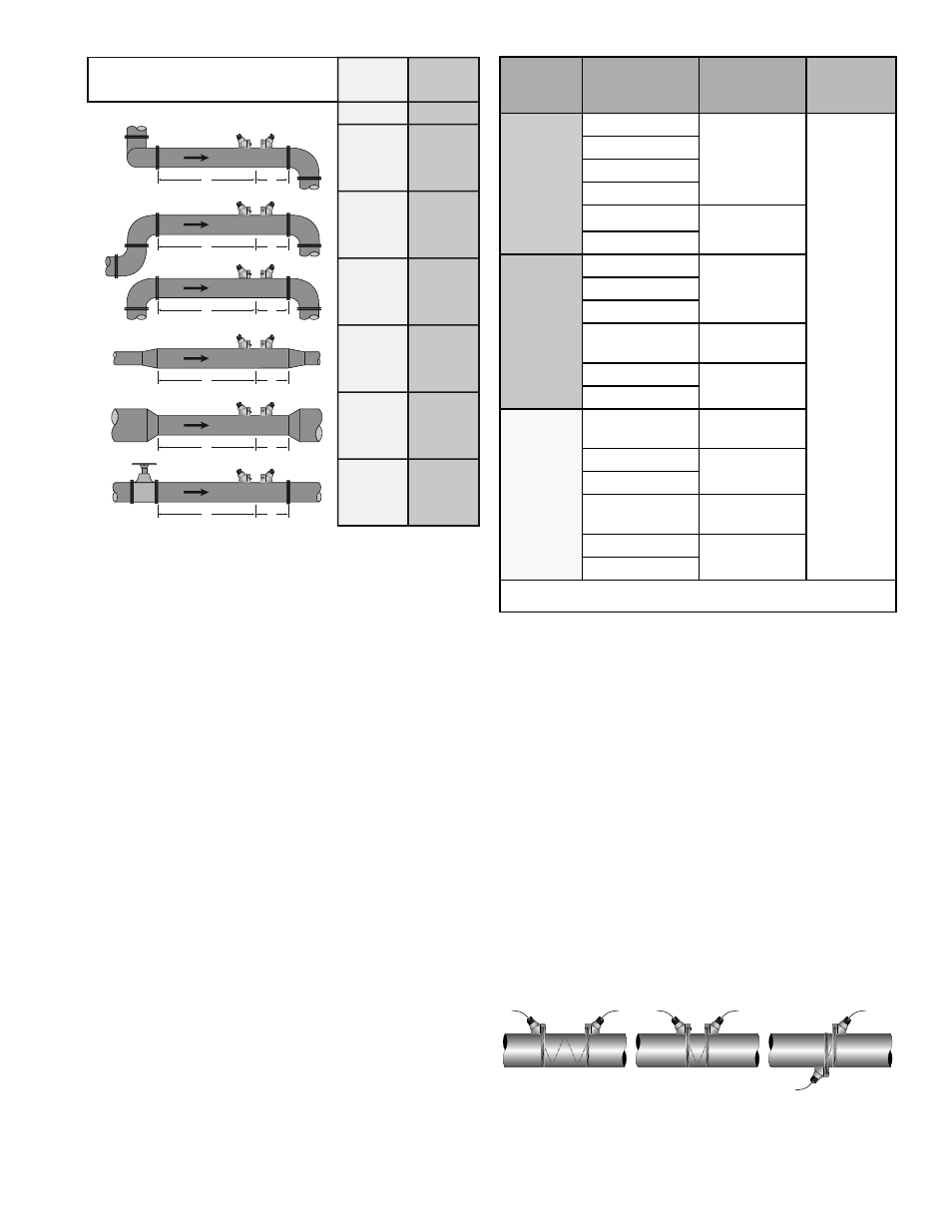
Piping Configuration
and Transducer Positioning
TABLE 2.1 - PIPING CONFIGURATION AND
TRANSDUCER POSITIONING
~ Mount the transducers in an area where they will not
be inadvertently bumped or disturbed during normal
operation.
~ Avoid installations on downward fl owing pipes unless
adequate downstream head pressure is present to over-
come partial fi lling of or cavitation in the pipe.
The fl ow meter system will provide repeatable measure-
ments on piping systems that do not meet these require-
ments, but accuracy of these readings may be infl uenced to
various degrees.
STEP 2 - TRANSDUCER SPACING
TFXL remote mount transit time fl ow meters can be used
with four diff erent transducer types: DTTN, DTTH, DTTS
and DTTC. Meters that utilize the DTTN or DTTH transducer
sets consist of two separate sensors that function as both
ultrasonic transmitters and receivers. DTTS and DTTC trans-
ducers integrate both the transmitter and receiver into one
assembly that fi xes the separation of the piezoelectric crys-
tals. DTTN and DTTH transducers are clamped on the outside
of a closed pipe at a specifi c distance from each other.
Transducer
Mount
Mode
Pipe Material
Pipe Size
Liquid
Composition
W-Mount
Plastic (all types)
2-4 in.
(50-100 mm)
Low TSS;
non-aerated
Carbon Steel
Stainless Steel
Copper
Ductile Iron
Not
recommended
Cast Iron
V-Mount
Plastic (all types)
4-12 in.
(100-300 mm)
Carbon Steel
Stainless Steel
Copper
4-30 in.
(100-750 mm)
Ductile Iron
2-12 in.
(50-300 mm)
Cast Iron
Z-Mount
Plastic (all types)
> 30 in.
(> 750 mm)
Carbon Steel
> 12 in.
(> 300 mm)
Stainless Steel
Copper
> 30 in.
(> 750 mm)
Ductile Iron
> 12 in.
(> 300 mm)
Cast Iron
TSS = Total Suspended Solids
TABLE 2.2 - TRANSDUCER MOUNTING MODES
— DTTN AND DTTH
The DTTN and DTTH transducers can be mounted in:
W-Mount where the sound traverses the pipe four
times. This mounting method produces the best relative
travel time values but the weakest signal strength.
V-Mount where the sound traverses the pipe twice.
V-Mount is a compromise between travel time and
signal strength.
Z-Mount where the transducers are mounted on oppo-
site sides of the pipe and the sound crosses the pipe
once. Z-Mount will yield the best signal strength but
the smallest relative travel time.
For further details, reference Figure 2.1. The appropriate
mounting confi guration is based on pipe and liquid char-
acteristics. Selection of the proper transducer mounting
method is not entirely predictable and many times is an
TOP VIEW
OF PIPE
W-Mount
V-Mount
Z-Mount
TOP VIEW
OF PIPE
TOP VIEW
OF PIPE
FIGURE 2.1- TRANSDUCER MOUNTING MODES —
DTTN AND DTTH