Part 2 – transducer installation – Dynasonics TFXL Clamp-On Ultrasonic Flow User Manual
Page 10
10
06-TTM-UM-00158 8/2012
NOTE: The transducer cable carries low level, high frequency
signals. In general, it is not recommended to add additional
length to the cable supplied with the transducers. If additional
cable is required, contact the factory to arrange an exchange
for a transducer with the appropriate length of cable. Cables
100 to 990 feet (30 to 300 meters) are available with RG59 75
Ohm coaxial cable. If additional cable is added, ensure that it is
the same type as utilized on the transducer. Twinaxial (blue and
white conductor) cables can be lengthened with like cable to
a maximum overall length of 100 feet (30 meters). Coaxial
cables can be lengthened with RG59 75 Ohm cable and BNC
connectors to 990 feet (300 meters).
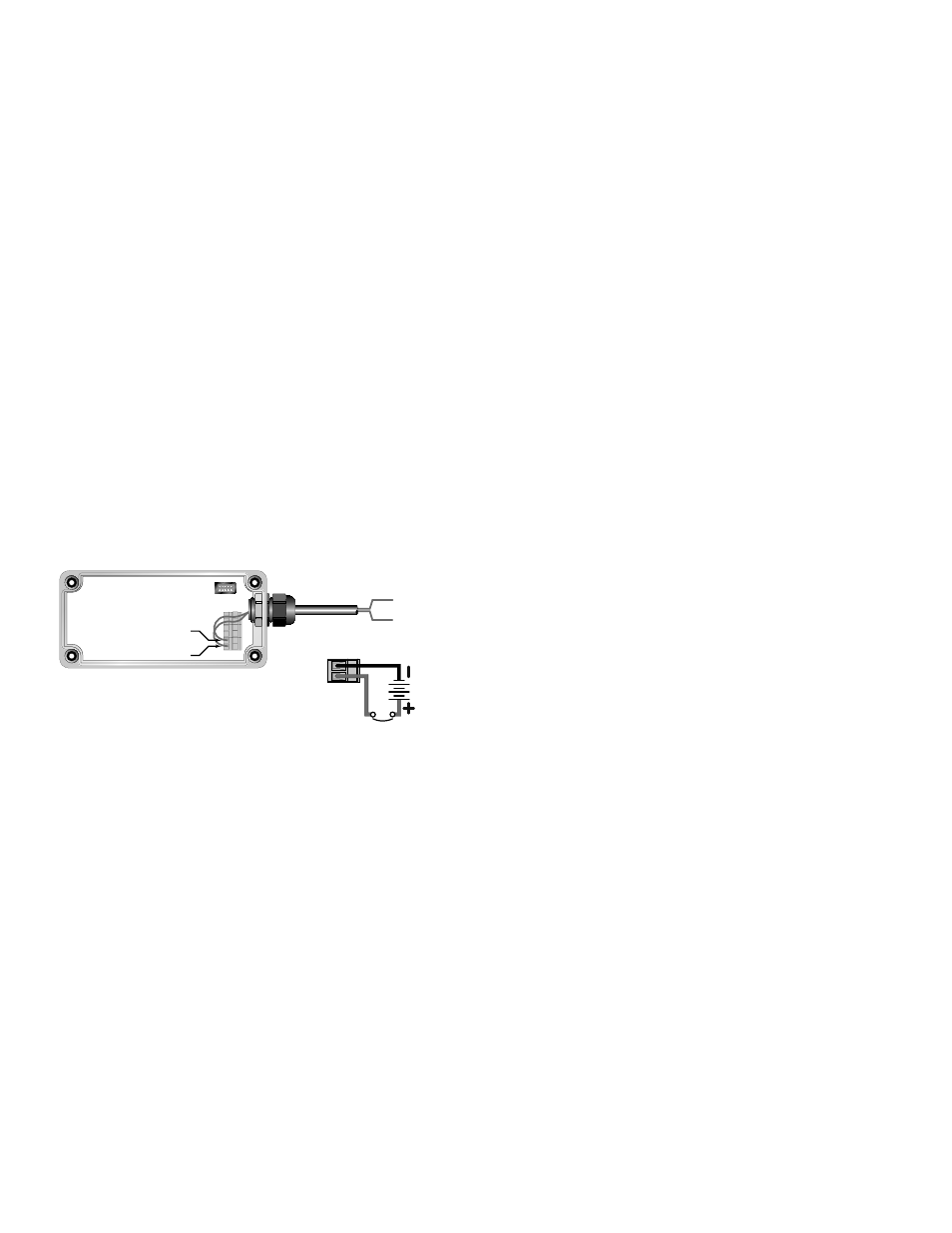
DC POWER CONNECTIONS
The TFXL should be operated from an 11 to 28 VDC Class 2
power source capable of supplying a minimum of 250 mA
of current.
Connect power to the screw terminal block in the TFXL trans-
mitter. See Figure 1.4. Utilize the conduit hole on the right
side of the enclosure for this purpose. Use wiring practices
that conform to local and national codes (e.g., The National
Electrical Code® Handbook in the U.S.)
Connect the DC power to 11 to 28 VDC In, and DC Gnd., as
in Figure 1.4.
DC Ground
11 - 28 VDC
DC Ground
11 - 28 VDC
FIGURE 1.4 - DC POWER CONNECTIONS
1) Connect an 11-28 VDC Class 2 power source as illus-
trated in the schematic in Figure 1.4. Wire up to 14
AWG can be accommodated in the TFXL terminal blocks
a) A switch or circuit breaker is required in the
installation.
b) The switch or circuit breaker must be in close
proximity of the TFXL and within easy reach of
the operator.
c) The switch or circuit breaker must be marked as
the disconnect device for the TFXL.
PART 2 – TRANSDUCER
INSTALLATION
GENERAL
The transducers that are utilized by the TFXL contain piezo-
electric crystals for transmitting and receiving ultrasonic
signals through walls of liquid piping systems. DTTN and
DTTH transducers are relatively simple and straightforward
to install, but spacing and alignment of the transducers is
critical to the system’s accuracy and performance. Extra care
should be taken to ensure that these instructions are care-
fully executed. DTTS and DTTC, small pipe transducers, have
integrated transmitter and receiver elements that eliminate
the requirement for spacing measurement and alignment.
Mounting of the DTTN and DTTH clamp-on ultrasonic transit
time transducers is comprised of three steps:
1) Selection of the optimum location on a piping system.
2) Entering the pipe and liquid parameters into the soft-
ware utility. The software utility will calculate proper
transducer spacing based on these entries.
3) Pipe preparation and transducer mounting.
STEP 1 - MOUNTING LOCATION
The fi rst step in the installation process is the selection of an
optimum location for the fl ow measurement to be made. For
this to be done eff ectively, a basic knowledge of the piping
system and its plumbing are required.
An optimum location is defi ned as:
~ A piping system that is completely full of liquid when
measurements are being taken. The pipe may become
completely empty during a process cycle – which will
result in the error code 0010 (Low Signal Strength)
being displayed on the fl ow meter while the pipe is
empty. This error code will clear automatically once the
pipe refi lls with liquid. It is not recommended to mount
the transducers in an area where the pipe may become
partially fi lled. Partially fi lled pipes will cause erroneous
and unpredictable operation of the meter.
~ A piping system that contains lengths of straight pipe
such as those described in Table 2.1. The optimum
straight pipe diameter recommendations apply to pipes
in both horizontal and vertical orientation. The straight
runs in Table 2.1 apply to liquid velocities that are
nominally 7 FPS (2.2 MPS). As liquid velocity increases
above this nominal rate, the requirement for straight
pipe increases proportionally.