Dynasonics TFXL Clamp-On Ultrasonic Flow User Manual
Page 12
12
06-TTM-UM-00158 8/2012
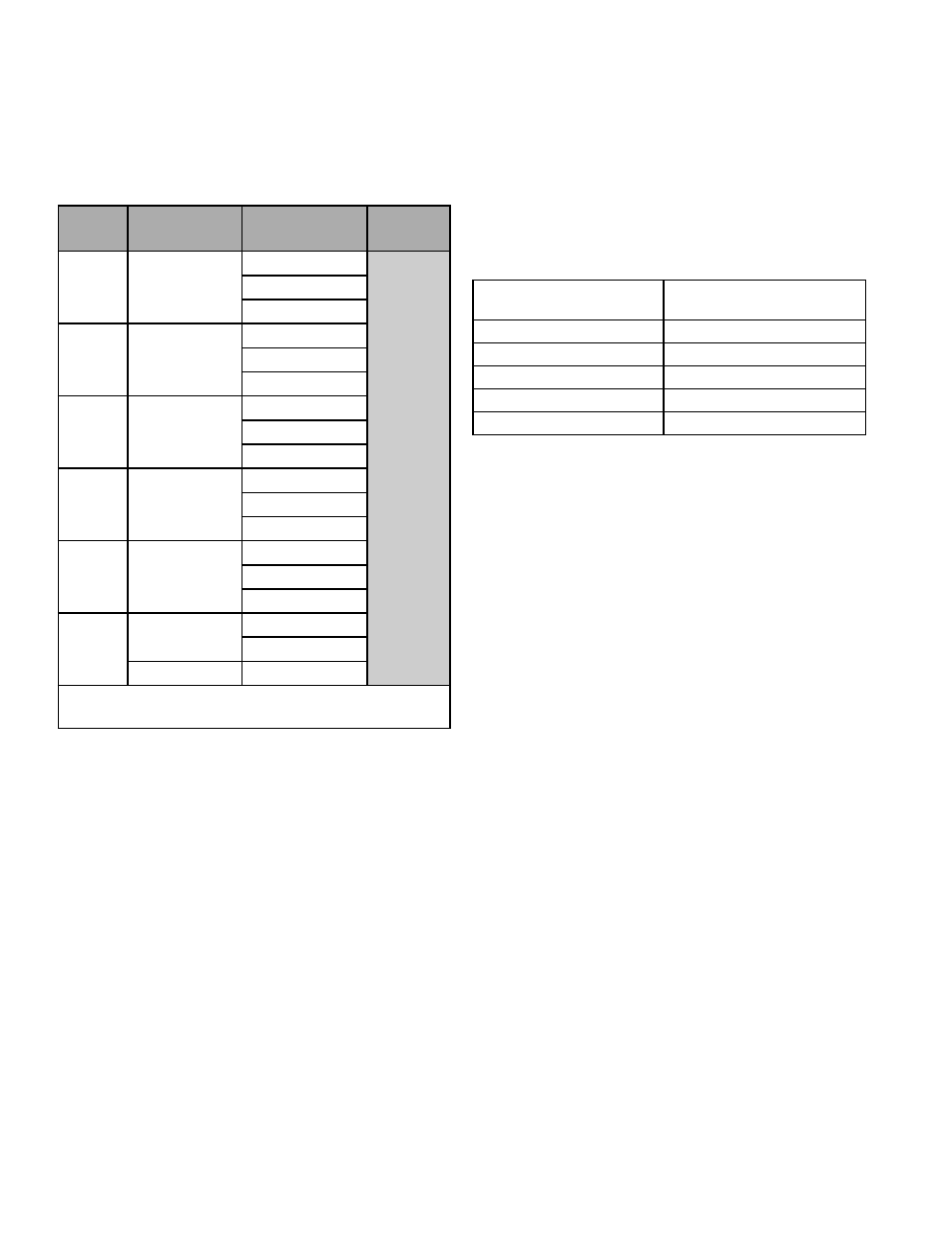
iterative process. Table 2.2 contains recommended mounting
confi gurations for common applications. These recom-
mended confi gurations may need to be modifi ed for specifi c
applications if such things as aeration, suspended solids, out
of round piping or poor piping conditions are present. Use of
the TFXL diagnostics in determining the optimum transducer
mounting is covered later in this section.
Size
Frequency
Setting
Transducer
Mounting
Mode
½
2 MHz
DTTSnP
V
DTTSnC
DTTSnT
¾
2 MHz
DTTSnP
DTTSnC
DTTSnT
1
2 MHz
DTTSnP
DTTSnC
DTTSnT
1¼
2 MHz
DTTSnP
DTTSnC
DTTSnT
1½
2 MHz
DTTSnP
DTTSnC
DTTSnT
2
1 MHz
DTTSnP
DTTSnC
2 MHz
DTTSnT
NOTE: DTTS transducer designation refers to both DTTS
and DTTC transducer types.
TABLE 2.3 - TRANSDUCER MOUNTING
MODES — DTTS / DTTC
STEP 3 - ENTERING PIPE AND LIQUID DATA
The TFXL system calculates proper transducer spacing by
utilizing piping and liquid information entered by the user.
This information can be entered on a TFXL via the software
utility.
The best accuracy is achieved when transducer spacing is
exactly what the TFXL calculates, so the calculated spacing
should be used if signal strength is satisfactory. If the pipe
is not round, the wall thickness not correct or the actual
liquid being measured has a diff erent sound speed than the
liquid programmed into the transmitter, the spacing can vary
from the calculated value. If that is the case, the transducers
should be placed at the highest signal level observed by
moving the transducers slowly around the mount area.
NOTE: Transducer spacing is calculated on “ideal” pipe.
Ideal pipe is almost never found so the transducer spacing
distances may need to be altered. An eff ective way to maxi-
mize signal strength is to confi gure the display to show signal
strength, fi x one transducer on the pipe and then starting
at the calculated spacing, move the remaining transducer
small distances forward and back to fi nd the maximum signal
strength point.
Important! Enter all of the data on this list, save the data and
reset the TFXL before mounting transducers.
The following information is required before programming
the instrument:
Transducer mounting
confi guration
Pipe O.D. (outside diameter)
Pipe wall thickness
Pipe material
Pipe sound speed
1
Pipe relative roughness
1
Pipe liner thickness (if present)
Pipe liner material (if present)
Fluid type
Fluid sound speed
1
Fluid viscosity
1
Fluid specifi c gravity
1
NOTE: Much of the data relating to material sound speed,
viscosity and specifi c gravity is pre-programmed into the TFXL
fl ow meter. This data only needs to be modifi ed if it is known
that a particular application’s data varies from the reference
values. Refer to Part 4 of this manual for instructions on
entering confi guration data into the TFXL fl ow meter via the
software.
1
NOMINAL VALUES FOR THESE PARAMETERS ARE INCLUDED
WITHIN THE TFXL OPERATING SYSTEM. THE NOMINAL
VALUES MAY BE USED AS THEY APPEAR OR MAY BE MODI-
FIED IF EXACT SYSTEM VALUES ARE KNOWN.
After entering the data listed above, the TFXL will calculate
proper transducer spacing for the particular data set. This
distance will be in inches if the TFXL is confi gured in English
units, or millimeters if confi gured in metric units.
STEP 4 - TRANSDUCER MOUNTING
PIPE PREPARATION
After selecting an optimal mounting location (Step 1) and
successfully determining the proper transducer spacing
(Step 2 & 3), the transducers may now be mounted onto the
pipe (Step 4).
Before the transducers are mounted onto the pipe surface,
an area slightly larger than the fl at surface of each transducer
must be cleaned of all rust, scale and moisture. For pipes with
rough surfaces, such as ductile iron pipe, it is recommended
that the pipe surface be wire brushed to a shiny fi nish. Paint
and other coatings, if not fl aked or bubbled, need not be
removed. Plastic pipes typically do not require surface prepa-
ration other than soap and water cleaning.
The DTTN and DTTH transducers must be properly oriented
and spaced on the pipe to provide optimum reliability and
performance. On horizontal pipes, when Z-Mount is required,