Target dbg data screen - definitions, Saving meter configuration on a pc, Printing a flow meter configuration report – Dynasonics TFXL Clamp-On Ultrasonic Flow User Manual
Page 24
24
06-TTM-UM-00158 8/2012
Next>
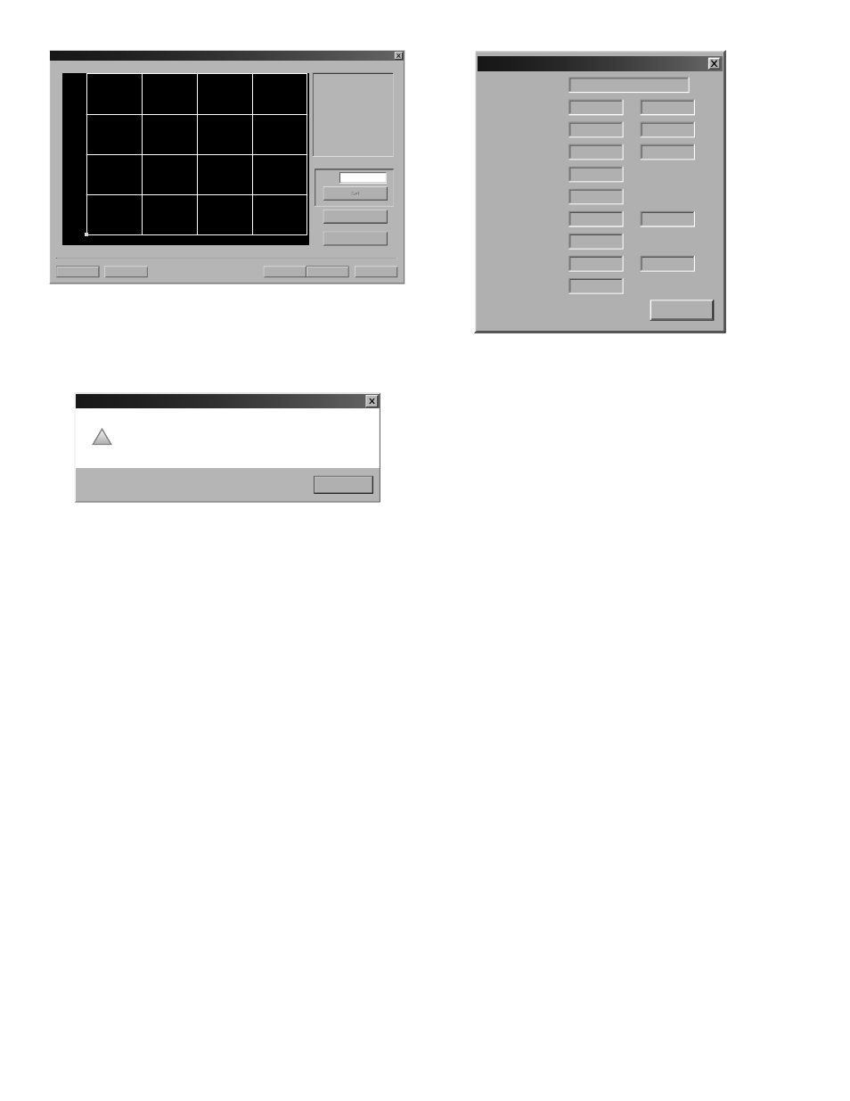
Cancel File Open... File Save... Calibration (Page 2 of 3) - General Setup 1) Please establish a 1FPS / 0.3MPS Minimum. 2) Enter the reference flow rate 3) Wait for flow to stablize. 4 Press the Set button. G al/MIN Delta Time Flow: Export... Edit FIGURE 4.9 - CALIBRATION PAGE 3 OF 3 Zero values are not valid for linearization entries. Flow meter Value can not be 0. UltraLINK OK ! Press the Finish button when all points have been entered. TARGET DBG DATA SCREEN - DEFINITIONS 1) Calc Count - The number of fl ow calculations performed 2) Sample Count - The number of samples currently being 4) Course Delta T - The TFX series uses two wave forms. The 5) Gain - The amount of signal amplifi cation applied to the 6) Gain Setting/Waveform Power - The fi rst number is the Target Dbg Data Reset Device Type: TFX Tx Delay: 413 7 Flow Filter: 80 8 Sound Speed: 4900 11 Serial No (TFXD): Calc Count: 2.2 CPS 54247 1 2 Raw Delta T (ns): 0 -10.73 3 4 Gain: 66/8 430 5 6 SS (Min/Max): OK 8.0/92.4 9 10 Reynolds: 0.7500 20.15 12 13 signal before the transmitter initiates another measurement 8) Flow Filter - The current value of the adaptive fi lter. 10) Signal Strength State - Indicates if the present signal 13) Reynolds Factor - The value applied to the fl ow calcula- SAVING METER CONFIGURATION ON A PC The complete confi guration of the fl ow meter can be saved PRINTING A FLOW METER CONFIGURATION REPORT Select File from the upper task bar and Print to print a cali-
reference flow rate.
below. (Do not enter 0)
zero is entered on Page 1 of 3. If a zero calibration point is
attempted, the following error message will be shown:
This value was already set in a previous screen (Page 1 of 3).
by the meter beginning at the time the power to the meter
was last turned off and then on again.
taken in one second.
3) Raw Delta T (ηs) - The actual amount of time it takes for
an ultrasonic pulse to cross the pipe.
coarse to fi nd the best delay and other timing measurements
and a fi ne to do the fl ow measurement.
refl ected ultrasound pulse to make it readable by the digital
signal processor.
gain setting on the digital pot (automatically controlled by
the AGC circuit). Valid numbers are from 1 to 100. The second
number is the power factor of the current waveform being
used. For example, “8” indicates that a 1⁄8 power wave form is
being used.
7) Tx Delay - The amount of time the transmitting transducer
waits for the receiving transducer to recognize an ultrasound
cycle.
9) SS (Min/Max) - The minimum and maximum signal
strength levels encountered by the meter beginning at the
time the power to the meter was last turned off and then on
again.
strength minimum and maximum are within a pre-
programed signal strength window.
11) Sound Speed - The actual sound speed being
measured by the transducers at that moment.
12) Reynolds - A number indicating how turbulent a fl uid
is. Reynolds numbers between 0 and 2000 are considered
laminar fl ow. Numbers between 2000 and 4000 are in transi-
tion between laminar and turbulent fl ows and numbers
greater than 4000 indicate turbulent fl ow.
tion to correct for variations in Reynolds numbers.
from the Confi guration screen. Select File Save button
located in the lower left-hand corner of the screen and
name the fi le. Files are saved as a *.dcf extension. This fi le
may be transferred to other fl ow meters or may be recalled
should the same pipe be surveyed again or multiple meters
programmed with the same information.
bration/confi guration information sheet for the installation.