Setting zero and calibration – Dynasonics TFXL Clamp-On Ultrasonic Flow User Manual
Page 23
06-TTM-UM-00158 8/2012
23
Flow at 4 mA / 0 Hz = -100.0
Flow at 20 mA / 1,000 Hz = 100.0
If the meter were a TFXL, this setting would also set the span
for the frequency output. At -100 GPM, the output frequency
would be 0 Hz. At the maximum fl ow of 100 GPM, the output
frequency would be 1,000 Hz, and in this instance a fl ow of
zero would be represented by an output frequency of 500 Hz.
Example 2 - To span the 4-20 mA output from 0 GPM to +100
GPM with 12 mA being 50 GPM, set the Flow at 4 mA / 0 Hz
and Flow at 20 mA / 1,000 Hz inputs as follows:
Flow at 4 mA / 0 Hz = 0.0
Flow at 20 mA / 1,000 Hz = 100.0
For the TFXL meter, in this instance, zero fl ow would be
represented by 0 Hz and 4 mA. The full scale fl ow or 100 GPM
would be 1,000 Hz and 20 mA and a midrange fl ow of 50
GPM would be expressed as 500 Hz and 12 mA.
4-20 Test -- 4-20 mA Output Test (Value)
Allows a simulated fl ow value to be sent from the 4-20 mA
output. By incrementing this value, the 4-20 mA output will
transmit the indicated current value.
Errors
Alarm outputs on any error condition. See Error Table in the
Appendix
of this manual.
SETTING ZERO AND CALIBRATION
Calibration
The software utility contains a powerful
multi-point calibration routine that can be
used to calibrate the TFXL fl ow meter to a
primary measuring standard in a particular installation. To
initialize the three-step calibration routine, click on the
Calibration button located on the top of the Data Screen.
The display shown in Figure 4.7 will appear.
The fi rst screen (Page 1 of 3) , establishes a baseline zero fl ow
rate measurement for the instrument. Because every fl ow
meter installation is slightly diff erent and sound waves can
travel in slightly diff erent ways through these various installa-
tions, it is important to remove the zero off set at zero fl ow to
maintain the meters accuracy. A provision is made using this
entry to establish “Zero” fl ow and eliminate the off set.
To zero the fl ow meter:
1) Establish zero fl ow in the pipe (ensure that the pipe
is full of fl uid, turn off all pumps, and close a dead-
heading valve). Wait until the delta-time interval shown
in “Current Delta T” is stable (and typically very close to
zero).
2) Click the Set button.
3) Click the Next button when prompted, then click the
Finish button on the calibration screen.
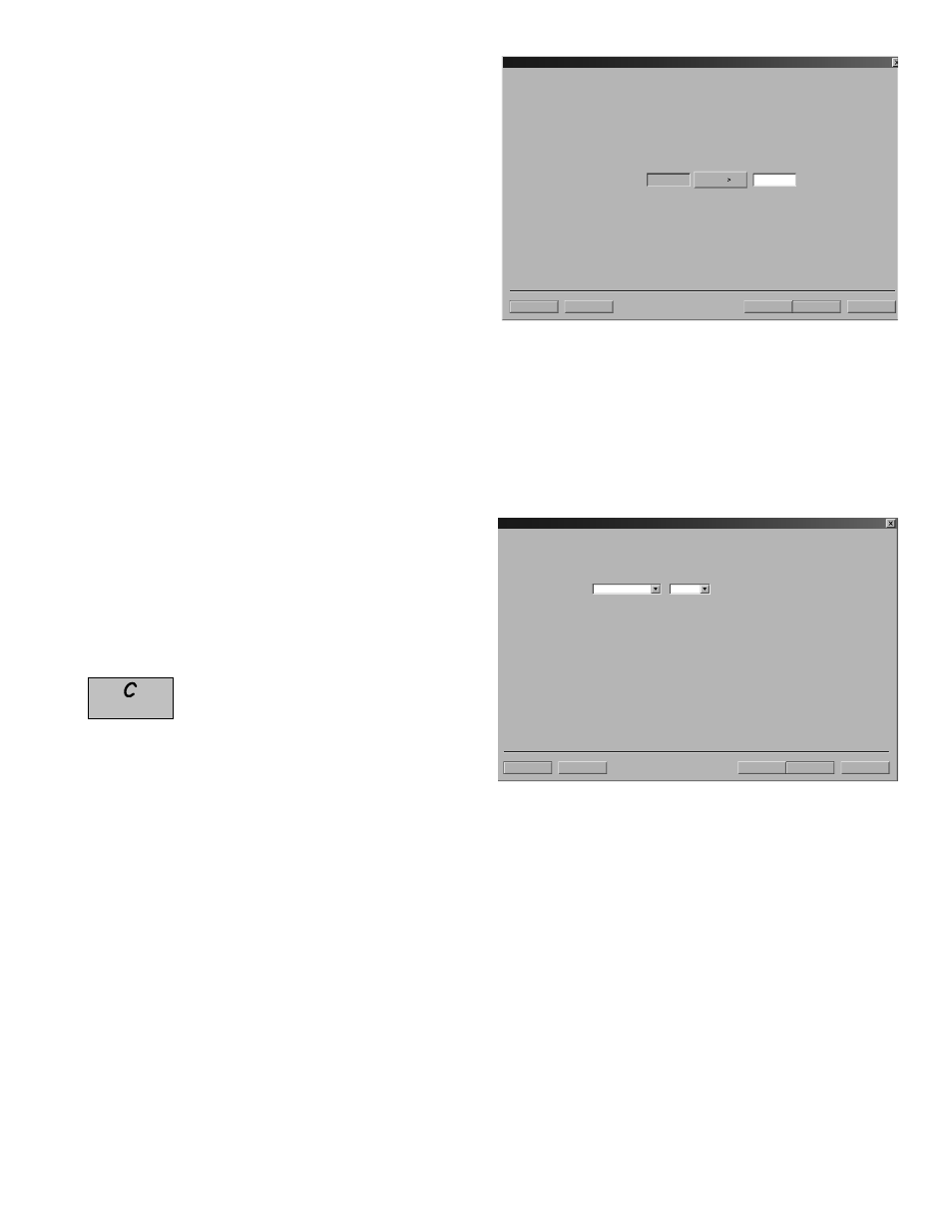
Next>
Cancel File Open... File Save... Calibration (Page 1 of 3) - Zero Flow Set -- -0.88 -0.43 Current Delta T: 1. Make sure flow is at zero. . FIGURE 4.7 - CALIBRATION PAGE 1 OF 3 The zeroing process is essential in systems using the DTTS The second step (Page 2 of 3) in the calibration process is the Next> Cancel File Open... File Save... Calibration (Page 2 of 3) - General Setup Gallons Min Flow Rate Units: / It is advisable to File Save the existing calibration before modifying it. If the Flow Rate Units selected on this page do not To view measurement units, go to Page 3 of 3 and press Edit. The Calibration Points Editor will show what units 1) If no data exists in the editor, selection of Flow Rate Units will not influence measurements. 2) If new calibration points are to be entered on Page 3 of 3, it is advisable to remove the existing calibration FIGURE 4.8 - CALIBRATION PAGE 2 OF 3 Page 3 of 3 as shown in Figure 4.9 allows multiple actual fl ow NOTE: If only two points are to be used (zero and span), it is
2. Wait for flow to stabilize.
3. Press
and DTTC transducer sets to ensure the best accuracy.
selection of the engineering units with which the calibration
will be performed. Select the Flow Rate Units and click the
Next button at the bottom of the window.
match the Flow Rate Units utilized for the existing data points collected on Page 3 of 3, flow measurement errors can occur.
were used during the existing calibration.
points using the Calibration Points Editor.
rates to be recorded by the TFXL. To calibrate a point, estab-
lish a stable, known fl ow rate (verifi ed by a real-time primary
fl ow instrument), enter the actual fl ow rate in the Figure 4.9
window and click the Set button. Repeat for as many points
as desired.
preferable to use the highest fl ow rate anticipated in normal
operation as the calibration point. If an erroneous data point
is collected, the point can be removed by pressing the Edit
button, selecting the bad point and then selecting Remove.