Basic tab general, Transducer, Figure 4.2 - data display screen – Dynasonics TFXL Clamp-On Ultrasonic Flow User Manual
Page 19: Configuration
06-TTM-UM-00158 8/2012
19
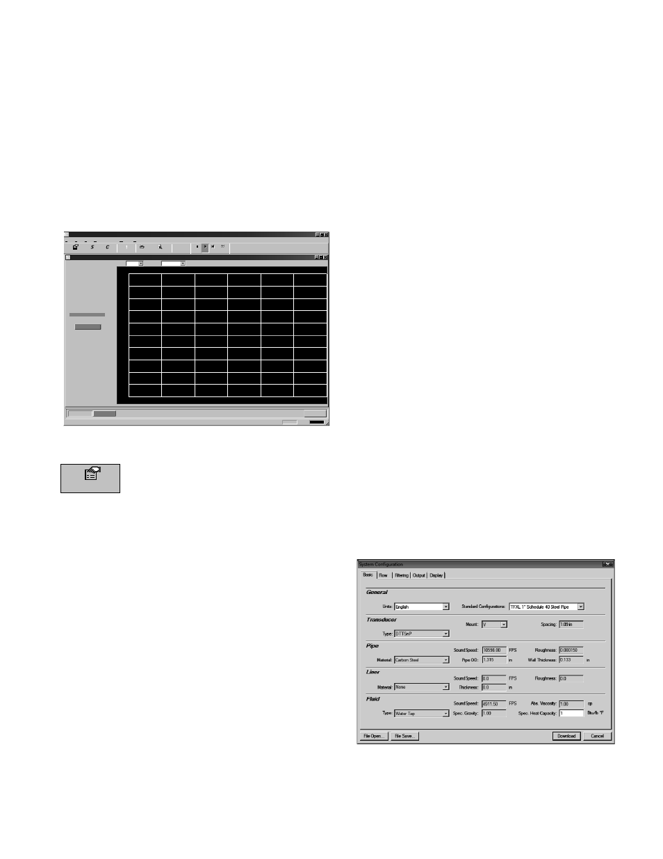
2) Double-click on the ULTRALINK icon. The fi rst screen is
the “RUN” mode screen (see Figure 4.2), which contains
real-time information regarding fl ow rate, totals, signal
strength, communications status, and the fl ow meter’s
serial number. The COMM indicator in the lower right-
hand corner indicates that the serial connection is
active. If the COMM box contains a red ERROR, click
on the Communications button on the Menu bar and
select Initialize. Choose the appropriate COM port and
the RS232 / USB Com Port Type. Proper communica-
tion is verifi ed when a green OK is indicated in the
lower right-hand corner of the PC display and the “Last
Update” indicator in the text area on the left side of the
screen changes from red to an active clock indication.
UltraLINK Device Addr 127
Data Display
Diagnostics
Device Addr 127
Reset Totalizers
Help
Window
Communications
View
Edit
File
About
?
?
Errors
rro
!
Configuration
Calibration
Strategy
Exit
OK
13:26:33 COMM:
For Help, press F1
Go
Stop
Stop
Stop
Step
View
-1.00:00
-2000
-1600
1600
-1200
-800
-400
2000
1200
800
400
0
-50:00
-40:00
-30:00
-20:00
-10:00
-0:00
Time (mm:ss)
Flow Rate
Historical Data
Scale:
Time:
60 Min
2000
135 Gal/Min
237 Gal
15.6%
100%
2.50 ns
Flow:
Totalizer Net:
Pos:
Neg:
Sig. Strength:
Margin:
Delta T:
Last Update: 12:17:20
0 Gal
237 Gal
Print Preview
U
U
Signal Strength too Low!
FIGURE 4.2 - DATA DISPLAY SCREEN
Configuration
The Confi guration drop-down houses six
screens used to control how the TFXL is set up
and responds to varying fl ow conditions. The
fi rst screen that appears after clicking the Confi guration
button is the Basic screen. See Figure 4.3.
BASIC TAB
GENERAL
The general heading allows users to select the measurement
system for meter setup, either English or Metric and choose
from a number of pre-programmed small pipe confi gura-
tions in the Standard Confi gurations drop-down. If pipe
measurements are to be entered in inches, select English. If
pipe measurements are to be entered in millimeters, select
Metric. If the General entries are altered from those at instru-
ment start-up, then click on the Download button in the
lower right-hand portion of the screen and cycle power to
the TFXL.
When using the Standard Confi gurations drop-down menu
alternate, menu choices can be made by using the following
guidelines:
1) Select the transducer type and pipe size for the trans-
ducer to be used. The fi rmware will automatically enter
the appropriate values for that pipe size and type. Every
entry parameter except for Units, Standard Confi gura-
tions, and Specifi c Heat Capacity will be unavailable
behind a “grayed out” entry box.
2) Go back to the Standard Confi gurations drop-down
menu and select Custom. As soon as Custom is chosen,
the previously grayed out selections will become avail-
able for editing.
3) Make any changes to the Basic confi guration deemed
necessary and press Download.
4) To ensure that the confi guration changes take eff ect,
turn the power off and then back on again to the
transmitter.
TRANSDUCER
Transducer Type selects the transducer that will be
connected to the TFXL fl ow meter. Select the appropriate
transducer type from the drop-down list. This selection
infl uences transducer spacing and fl ow meter performance,
so it must be correct. If you are unsure about the type of
transducer to which the TFXL will be connected, consult the
shipment packing list or call the manufacturer for assistance.
NOTE: A change of Transducer Type will cause a System
Confi guration Error (1002: Sys Confi g Changed) to occur. This
error will clear when the microprocessor is reset or power is
cycled on the fl ow meter.
Transducer Mount selects the orientation of the transducers
on the piping system. See Part 2 of this manual and Table
2.2 for detailed information regarding transducer mounting
modes for particular pipe and liquid characteristics. When-
ever Transducer Mount is changed, a download command
and subsequent microprocessor reset or fl ow meter power
cycle must be conducted.
FIGURE 4.3 - BASIC TAB