Installation instructions, Part numbers – Draw-Tite 4448 GOOSENECK RAIL KIT User Manual
Page 8
Installation Instructions
Part Numbers:
4448
GOOSENECK MOUNTING KIT
Ford F-250/F-350 Super Duty
Will not fit Cab-on-Chassis vehicles
5/8” X 2.50 GR5 Carriage Bolt
Lockwasher
19
15
I t ll th 5/8” X 2 50 GR5
i
b lt th
h th hit h hi
d
b
S
ith l k
h
d
t
Lockwasher
Hex Nut
4 Places
19
15.
Install the 5/8” X 2.50 GR5 carriage bolts through the hitch, shims and cross members. Secure with lock washers and nuts.
Torque nuts to 150 Lb.-Ft.
16.
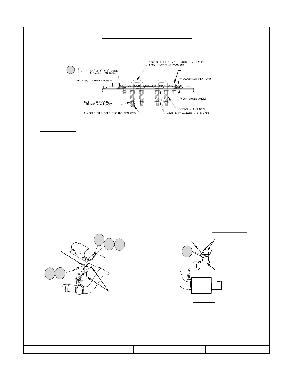
For 6300 and 8339 Installations: Install the (2) U-Bolts through the hitch. From under the vehicle install large flat washer
over the U-Bolt followed by a spring, another large flat washer and secure with a thin 5/8” jam nut. Repeat for other legs of the
U-Bolts. The 5/8” jam nuts are tightened until 3 threads are visible past the bottom of the jam nut.
17.
Torque the 5/8-11 GR5 fasteners connecting the rearward cross member to the brackets to 150 ft.-lb. (203 N-m).
18.
On gas vehicles only: Use the factory flange nut that was removed in step 2 to tighten the tube holder onto the L-bracket and
shown in figure 2c.
19.
Reinstall exhaust as shown below.
Exhaust installation:
Exhaust installation:
20.
If there is less than ½” clearance between the exhaust pipe and the cross members, the exhaust bracket supplied with the
4448 mounting kit must be used (See figure 6a and 6b). For the rear attachment (Figure 6a), fasten the supplied bracket
extension to the factory bracket with the factory M8 bolts, then fasten the extension to the frame with the supplied hardware.
Reattach the exhaust bracket forward of the axle to the frame cross member with 3/8” spacers sandwiched between the
bracket and cross member.
Factory nuts
Frame cross
member
Exhaust
bracket
16
13
14
15
Figure 6b
Center Attachment
Mounting
bracket
Factory
bolts
Figure 6a
Rear Attachment
14
15
z
2010 Cequent Performance Products
Sheet 8 of 8
4448N
3-22-10
Rev. A