Installation instructions, Part numbers, Figure 2b – Draw-Tite 4448 GOOSENECK RAIL KIT User Manual
Page 2: Figure 2c figure 2d, Figure 2a, Figure 3
Installation Instructions
Part Numbers:
4448
NOTES:
¾
This rail kit can be used with a 9460 or 9470 head only.
¾
Al
k
th b ll i f ll l
k d b f
t
i
GOOSENECK MOUNTING KIT
Ford F-250/F-350 Super Duty
Will not fit Cab-on-Chassis vehicles
¾
Always make sure the ball is fully locked before towing.
¾
Keep the ball and ball sleeve well lubricated.
¾
Periodically re-torque all the hitch fasteners.
¾
Check ball, hitch coupler, safety chains and other connections for proper operation every time you tow.
Warning:
The tow vehicle manufacturers recommended towing capacities should UNDER NO CIRCUMSTANCES be exceeded.
Check for adequate clearance between the gooseneck trailer and the rear of the cab and the rear of the truck box before installing hitch.
All trucks have fuel lines, brake lines and electrical wiring located along the vehicle frame where the rail kit installs. Carefully examine the
location of fuel lines, brake lines and electrical wires before installation and be certain not to damage these when positioning the hitch
components Be careful when drilling holes cutting sheet metal and tightening fasteners as to not limit the integrity of these systems
components. Be careful when drilling holes, cutting sheet metal and tightening fasteners as to not limit the integrity of these systems.
Hide-A-Goose Installation Instructions
1.
Lower the vehicle exhaust.
2.
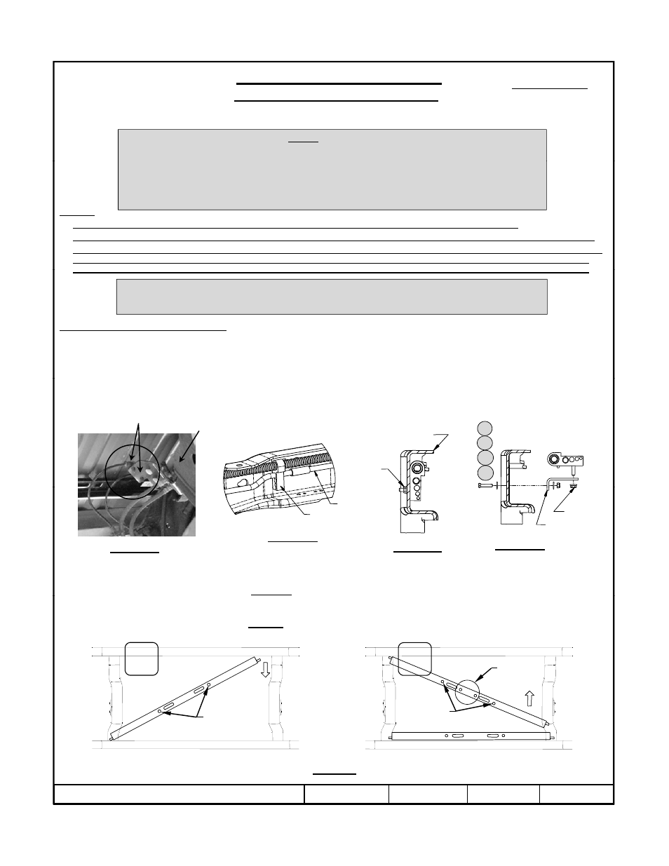
Use the provided cable tie to relocate the lines connected to the bracket on the driver’s side of the vehicle, shown in Figure 2a.
2b.
On Gas Engine Vehicles Only. The vapor tube running along the inside of the driver’s side frame rail must be relocated
prior to installing the driver’s side bracket (see Figure 2b). Remove the flange nut from the outside of the frame and keep for
Hide-A-Goose Only – Drilled hole in bed location (see step 8).
Short Box & Long Box – 46-3/16 inches
p
g
(
g
)
g
p
later use (see Figure 2c). Rotate the tubes up and out of the way. Install the L-bracket with 1/4” hardware, as shown in
Figure 2d. Tighten the L-bracket to the frame, but leave the tube holder loose to aid bracket installation. The tube holder will
be tightened onto the L-bracket in Step 12.
Driver’s side
frame rail
Driver’s side
frame rail
Existing
flange nut
11
12
11
10
Fuel Tank
Relocate Lines
3.
Place 5/8” GR8 carriage bolts from the 9460/9470 fastener kit into the square holes on the forward and rearward cross
members from the top pointing towards the ground. The forward cross member has two additional holes (see figure 3).
4.
From underneath the vehicle, install the rearward hitch cross member by placing one end above the vehicle frame and
Vapor
tube
Tube
holder
Figure 2b
Inside of frame rail
Figure 2c
Figure 2d
L-bracket
Existing
flange nut
Figure 2a
F
r
a
F
r
a
Front Hat Channel
maneuvering the notched section of the opposite end, above the vehicle frame. Temporarily position the rearward hitch cross
member against the rear hat channel of the vehicle.
5.
From underneath the vehicle install the forward hitch cross member by placing the driver’s side notched end above the
vehicle frame and maneuvering the opposite notched end above the exhaust and above the vehicle frame.
F
r
a
F
r
a
Front Hat Channel
Additional
Holes
a
m
e
a
m
e
Rear Hat Channel
z
2010 Cequent Performance Products
Sheet 2 of 8
4448N
3-22-10
Rev. A
a
m
e
a
m
e
Rear Hat Channel
Rear Cross Member
Installation
Forward Cross Member
Installation
Figure 3
Carriage
Bolts
Carriage
Bolts