Installation instructions, Part numbers, Figure 4 – Draw-Tite 4448 GOOSENECK RAIL KIT User Manual
Page 7
Installation Instructions
Part Numbers:
4448
5.
Loosely install the driver’s side and passenger’s side hitch side brackets by attaching the 5/8” hardware to the threaded studs.
Install the 5/8 X 2.50 carriage bolts through the hitch side brackets, 5/8” blocks and the large slots in the vehicle frame rails.
Loosely, install the 5/8 Conical Toothed Washers and 5/8 hex nuts to the carriage bolts (see Figure 1).
GOOSENECK MOUNTING KIT
Ford F-250/F-350 Super Duty
Will not fit Cab-on-Chassis vehicles
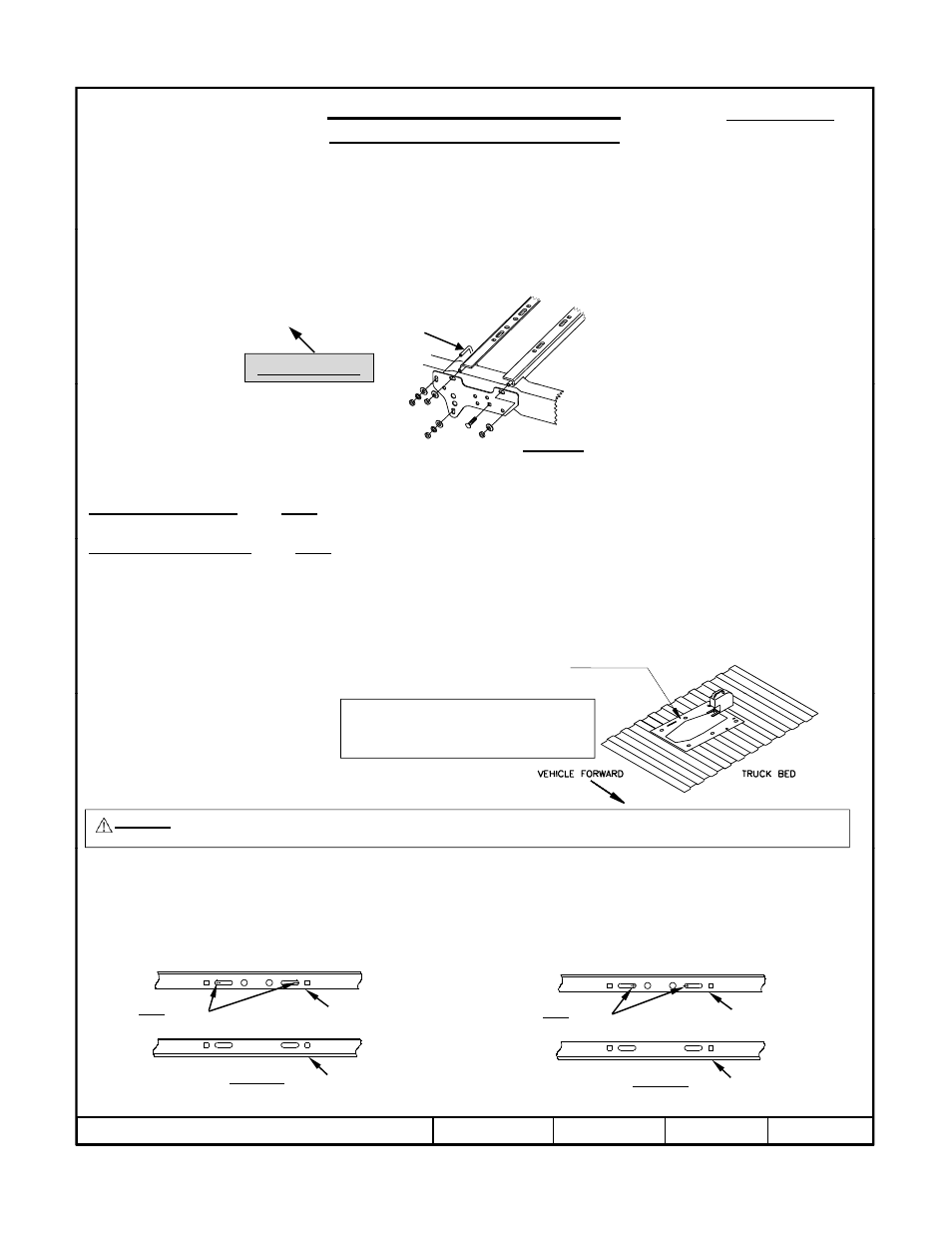
6.
Use the supplied U-Bolt for the forward attachment of the bracket to the frame (see Figure 4). Position U-Bolt from the inside
of the vehicle frame pointing towards the hitch side bracket. On the passenger’s side of the vehicle, the U-Bolt must be
positioned to the vehicle forward side of the shock mount and installed on an angle through the mounting slots on the hitch side
bracket.
Vehicle Forward
U-Bolt
7.
Torque the 5/8”-11 GR5 fasteners connecting the forward cross member to the brackets to 150 ft.-lb. (203 N-m). Torque the
1/2”-13 U-Bolt fasteners to 75 ft.-lb (102 N-m). Torque the 5/8” nuts to the 5/8 X 2.50 carriage bolts to 150 ft.-lb. (203 N-m).
The rearward cross member should be left loose until step 17.
8a.
For 6300 & 8339 use the outer edges of the long slots in the forward cross member as a template to drill 5/8” diameter holes
through the truck bed as shown in Figure 5a. Not all holes can be drilled from under the vehicle, but will be done later from
inside the bed.
Figure 4
8b.
For 83391 & 83399 use the inner edges of the long slots in the forward cross member as a template to drill 5/8” diameter
holes through the truck bed as shown in Figure 5b. Not all holes can be drilled from under the vehicle, but will be done later
from inside the bed.
9.
Align the holes on the template (provided with the gooseneck hitch) with the holes previously drilled through the bed. Be sure
that the template is properly oriented toward the front of the vehicle. Center punch the holes that will be used to cut the
opening in the bed. If the vehicle is equipped with a bed liner, a section of the bed liner must be cut away so that the gooseneck
hitch can contact the bed corrugations.
10.
Drill 1/4” pilot holes (size will depend on width of blade in saber saw). Cut out the truck bed, file the edges as needed.
11.
Install the hitch into the opening.
Template p/n 5978 for use with 6300 head
Template p/n 114234 for use with 8339 head
Template p/n 114523 for use with 83399/83391 heads
WARNING The fuel tank and/or other vehicle components are located below some of the holes. A wood or metal shield must be
placed between the frame and the fuel tank to prevent puncturing the fuel tank when the drill breaks through the bed.
Durable and reusable stainless steel templates are also
available. A time saver for cutting bed liner and bed.
Template p/n 6467 for use with 6300 head
Template p/n 6425 for use with 8339 head
Template p/n 58384 for use with 83399/83391 heads
12.
Use the hitch as a guide to drill the 5/8” diameter holes for the rearward cross member. Also, drill 5/8” diameter U-Bolt holes
if installing a 6300 or 8339 gooseneck hitch.
13.
Before installing the 5/8” carriage bolts through the hitch, the U-Block shims (Part Number 5994) must be placed between
the hitch and the bed and between the cross members and the bottom of the bed. These shims are necessary to prevent the
bed corrugations from collapsing when the bolts are tightened.
14.
Align the rearward cross member with the 5/8 diameter drilled holes.
F
d
6300/8339 Hole Locations
83399/83391 Hole Locations
z
2010 Cequent Performance Products
Sheet 7 of 8
4448N
3-22-10
Rev. A
Forward cross
member
Rearward cross
member
Use outer edges to
drill 5/8” holes
Figure 5a
Forward cross
member
Use inner edges to
drill 5/8” holes
Figure 5b
Rearward cross
member