Draw-Tite 24835 SPORTFRAME HITCH User Manual
Installation instructions, Mitsubishi galant, Part numbers
Installation Instructions
Mitsubishi Galant
Part Numbers:
77209
24835
60237
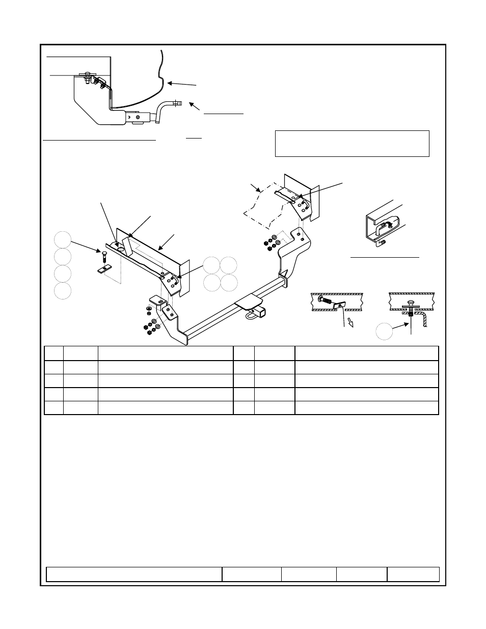
Hitch Shown In Proper Position
Wiring Access Location: TBD
Equipment Required: Torque wrench
Wrenches: 9/16 socket, ¾ socket, 6” extension
Drill Bits: None
1.
Lower exhaust by removing bolt in rubber hanger. Bend heat shield slightly to allow clearance for hitch side bracket.
2.
Using the pull wire provided, install carriage bolt and spacer into frame rail (driver’s side) through the access hole and into
the rearmost hole in the bottom of the frame rail. See figure 3.
3.
Install U-bolts into the rear angled section of the frame as shown. See figure 2.
4.
Raise hitch into position, being careful not to push the fasteners into the frame.
5.
Install the conical toothed washer, ½ hex nut onto carriage bolt.
6.
Install 3/8 flat washers, lock washers, and hex nuts onto u-bolts as shown.
7.
Tighten all fasteners to specified torque below.
8.
Re-install the exhaust lowered in step one.
Rev. B
3-3-09
24835N
Sheet 1 of 3
z
2009 Cequent Towing Products
Hex Nut, 3/8-16
Qty. (4)
9
Hex Nut ½-13
Qty. (1)
4
Lock Washer, 3/8
Qty. (4)
8
Conical Toothed Washer ½”
Qty. (1)
3
Pull wire, 1/2
Qty. (1)
5
Flat Washer, 3/8-16
Qty. (4)
7
Spacer 1/4” x 1 x 3
Qty. (1)
2
U-Bolt, 3/8-16 x 1.06 GR5
Qty. (2)
6
Carriage Bolt ½-13 x 1.75 GR5
Qty. (1)
1
Tighten all ½-13 GR5 fasteners with torque wrench to 75 Lb.-Ft. (102 N*M)
Tighten all 3/8-16 GR5 fasteners with torque wrench to 30 Lb.-Ft. (41 N*M)
Note: check hitch frequently, making sure all fasteners and ball are properly tightened. If hitch is removed, plug all holes in trunk pan or other body panels to
prevent entry of water and exhaust fumes. A hitch or ball which has been damaged should be removed and replaced. Observe safety precautions when working
beneath a vehicle and wear eye protection. Do not cut access or attachment holes with a torch.
This product complies with safety specifications and requirements for connecting devices and towing systems of the state of New York, V.E.S.C. Regulation V-5
and SAE J684.
2000 LB (908 Kg.) Max Gross Trailer Weight
200 LB (90.8 Kg.) Max Tongue Weight
Do Not Exceed Lower of Towing Vehicle
Manufacturer’s Rating or
Drawbar must be used in the
RISE position only.
Drawbar Kit:
3593
Fastener Kit: 24835F
Form F206 Rev A 5605
Fascia
Vehicle Frame
1
2
3
4
5
Figure 1.
Figure 3.
6 7
Access Hole
Angle Plate In Frame
Heat Shield
Bend Heat Shield to clear bracket
Figure 2.
U-BOLT INSTALLATION
Insert one end of U-bolt into frame and
rotate into position through frame
8 9