Draw-Tite 24869 SPORTFRAME HITCH User Manual
Installation instructions, Mazda 2, Part numbers
Installation Instructions
Mazda 2
Part Numbers:
24869, 60286
77252,
24844 u-haul
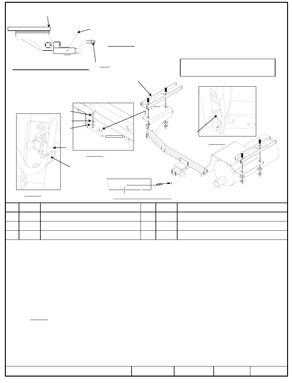
Hitch Shown In Proper Position
Wiring Access Location: PC3 & 4
Equipment Required: Bolt leader (provided),
Lubricant or Soapy water
Wrenches: Pliers, 10mm, (2) 7/16” & 11/16”
Access opening
end of frame rails
Kink pull wire to keep block
independent of bolt
1.
Lower exhaust system at the rubber isolators (2). Note: Spraying a lubricant or soapy water on the metal hanger rod and the rubber
isolator helps removal.
2.
Lower the carbon canister hose bracket from driver’s side frame rail. Return bolt to owner.
3.
Using a bolt leader insert carriage bolts and spacers into the access opening of the vehicle’s frame rail both sides as shown in Figure 1.
Leave the bolt leaders attached to bolts until the hitch is in place. On the passenger side with the bolt leaders attached leave the
carriage bolt in side the frame for extra clearance for the hitch bracket.
4.
Carefully raise the hitch into position over the muffler. Feed bolt leader through slots on the hitch. Maneuver hitch bracket between
rubber isolator on the exhaust hanger and frame rail on the passenger side first. Then pull fasteners through the frame rails with the bolt
leaders.
5.
Lift the hitch into position on the driver’s side using care around the carbon canister hoses. Be careful not to poke yourself with the ends
of the bolt leaders. Pull all fasteners through with the bolt leaders.
6.
Install conical washer and nuts onto bolts securely without tightening to hold hitch in place.
7.
Install the ¼” bolt, flat washer and lock washer through the round hole of the hitch on drivers side see Figure 2.
8.
Raise the carbon canister hose bracket into the new location secure with remaining fastener see Figure 3. Check that carbon c anister
hose does not contact the hitch bracket, if so use pliers to rotate hose out of the way.
9.
Check to ensure hitch is centered on vehicle and tighten all fasteners to torque specifications.
10. Raise muffler back into position.
z
2011 Cequent Performance Products
– Printed in Mexico
Sheet 1 of 3
24869N
5-27-11
Rev. C
j
Qty. (4)
Carriage bolt 7/16-14 X 1.50 GR5
n
Qty. (1)
Hex bolt ¼-20 X 1.25
k
Qty. (4)
Spacer
o
Qty. (1)
Lock washer 1/4”
l
Qty. (4)
Conical washer 7/16”
p
Qty. (1)
Flat washer 1/4”
m
Qty. (4)
Hex nut 7/16-14
q
Qty. (1)
Hex nut ¼-20
Tighten all 7/16-14 GR5 fasteners with torque wrench to 50 Lb.-Ft. (68 N*M)
Tighten all ¼-20 fasteners with torque wrench to 8 Lb.-Ft. (11 N*M)
Note: check hitch frequently, making sure all fasteners and ball are properly tightened. If hitch is removed, plug all holes in trunk pan or other body panels to prevent
entry of water and exhaust fumes. A hitch or ball which has been damaged should be removed and replaced. Observe safety precautions when working beneath a
vehicle and wear eye protection. Do not cut access or attachment holes with a torch.
This product complies with safety specifications and requirements for connecting devices and towing systems of the state of New York, V.E.S.C. Regulation V-5 and
SAE J684.
Do Not Exceed Lower of Towing Vehicle
Manufacturer’s Rating or
Drawbar must be used in the
RISE position only.
Drawbar Kit:
3593
Fastener Kit: 24869F
Form F206 Rev A 5605
2000 LB (908 Kg) Max Gross Trailer Weight
200 LB (90.8 Kg) Max Tongue Weight
Frame rail
Fascia
Example of pull wire procedure
Frame rail
j
k
l
m
n
o
q
p
Figure 1.
Rubber isolator
not shown
Figure 2.
Figure 3.
Carbon canister
hose bracket