Draw-Tite 24805 SPORTFRAME HITCH User Manual
Installation instructions, Ford focus
Installation Instructions
Ford Focus
Part Numbers:
60886
24805
77176
Do Not Exceed Lower of Towing Vehicle
Drawbar Kit:
3593
Frame rail
Fascia
Notch
24786
U-Haul
Hitch Shown In Proper Position
Wiring Access Location: PC1, 2
Equipment Required: Tin Snips
Do Not Exceed Lower of Towing Vehicle
Manufacturer’s Rating or
Drawbar must be used in the
Rise position only.
3593
Fastener Kit: 24805F
Frame rail
Spacer
(Item 2)
2000 LB (908 Kg) Max Gross Trailer Weight
200 LB (90.8 Kg) Max Tongue Weight
2
Install spacer between
hitch and frame.
Both sides
Wrenches: 10mm, 11/16
Fastener Kit: 24805F
1
2
7
6
4
Kink Pull wire to keep
spacer independent of bolt
Access hole at
end of rails
1
5
Both sides.
2
1
8
1
Qty. (6)
Carriage bolt 7/16-14 X 1.50 GR5
5
Qty. (4)
Spacer, small
2
Qty (4)
Spacer large
6
Qty (4)
Lock washers
3
4
1
5
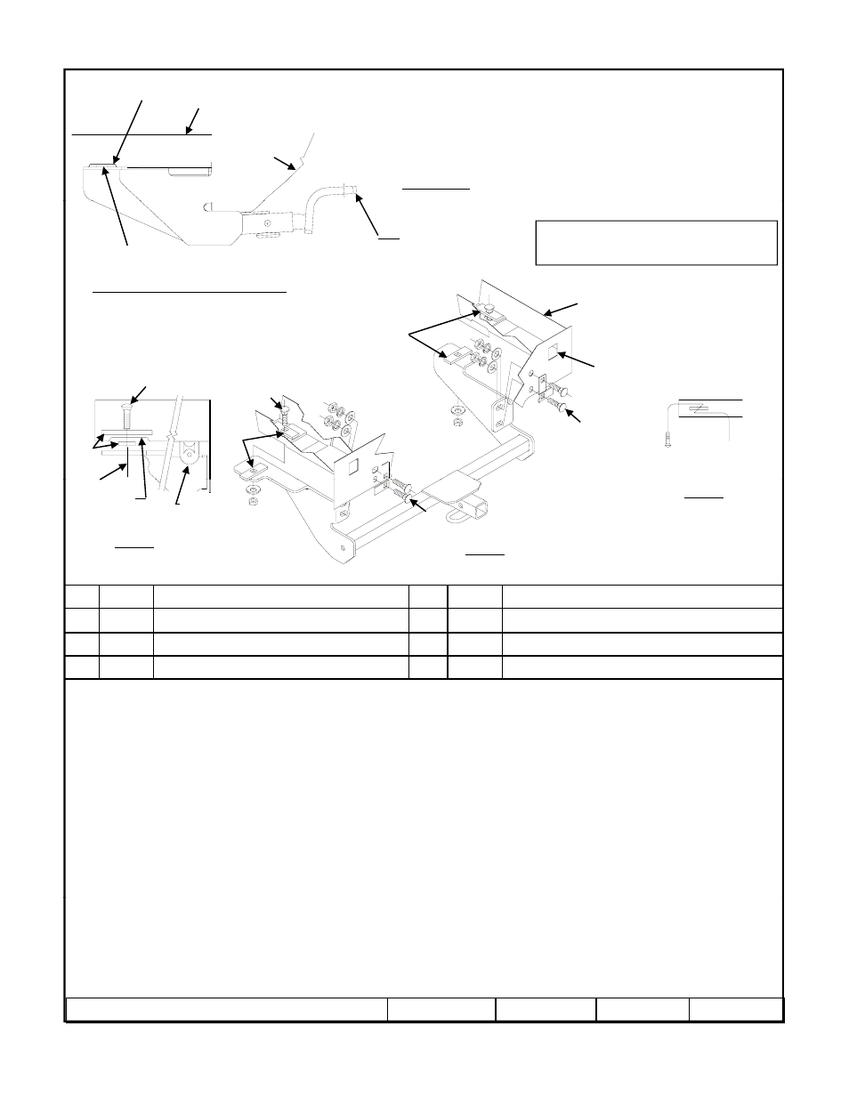
Figure 3
Figure 1
Figure 2
Fasteners typical both sides.
Notch
Exhaust, heat shield
and trunk not shown.
Rubber
isolator
Drivers frame rail
NOTE! Orient blocks
(Item 5) as shown
8
1.
Lower exhaust system at the rubber isolator. Spraying a lubricant on the metal hanger rod and the rubber isolator helps removal.
2.
Loosen the heat shield by removing the nuts. Note: heat shield cannot be removed.
3.
Trim heat shield around the notch at the attachment hole. See Figure 2.
4.
Bend heat shield back into position and re-install nuts.
2
Qty. (4)
Spacer, large
6
Qty. (4)
Lock washers
3
Qty. (2)
Conical washers
7
Qty. (4)
Flat washer
4
Qty. (6)
Hex nuts 7/16-14
8
Qty. (2)
Pull wire 7/16 (not shown)
5.
Using pull wires, feed spacers (Item 2) and carriage bolts into position (both rail). Access hole located at end of the frame rail and before the
impact bar. Leave pull wire attached. Note: It is much easier if bolt and spacer are not engaged while inserting them into frame, refer to
illustration. See Figure 3
6.
Install spacer (Item 2) between hitch and frame. Both sides. See Figure 2
7.
Raise hitch into position over the exhaust. Sandwiching the heat shield between the hitch and the rail on the drivers side.
8.
Remove pull wires and attach conical washers and nut (be careful not to push fastener back into frame rail).
9.
Install remaining fasteners as shown above. Figure 1. NOTE! Orient blocks (Item 5) as shown. (Blocks must not overlap)
10.
Torque all fasteners to specifications.
11
Raise exhaust system back into position
11.
Raise exhaust system back into position.
Tighten all 7/16-14 GR5 fasteners with torque wrench to 50 Lb.-Ft. (68 N*M)
z
2007, 2011 Cequent Performance Products
Sheet 1 of 3
24805N
4-20-11
Rev. B
Note: check hitch frequently, making sure all fasteners and ball are properly tightened. If hitch is removed, plug all holes in trunk pan or other body panels to
prevent entry of water and exhaust fumes. A hitch or ball which has been damaged should be removed and replaced. Observe safety precautions when working
beneath a vehicle and wear eye protection. Do not cut access or attachment holes with a torch.
This product complies with safety specifications and requirements for connecting devices and towing systems of the state of New York, V.E.S.C. Regulation V-5
and SAE J684.
Form F206 Rev A 5605