Chapter 2 - printer setup 4 interface connection, Sdio and usb host port connections – Datamax-O'Neil M-Class Mark II Operator’s Manual User Manual
Page 10
Chapter 2 - Printer Setup
4
Interface Connection
The printer can be connected to the host via the parallel, USB, serial, or optional network
interface. The printer will automatically connect to the first port that delivers valid data. Once
established, the printer’s power must be cycled ‘Off’ and ‘On’ to change an interface connection.
A couple of Optional Ethernet Print Servers (wired and wireless) are available. For
information on using these interfaces, refer to the instructions included with the option for proper
cabling, setup, and configuration.
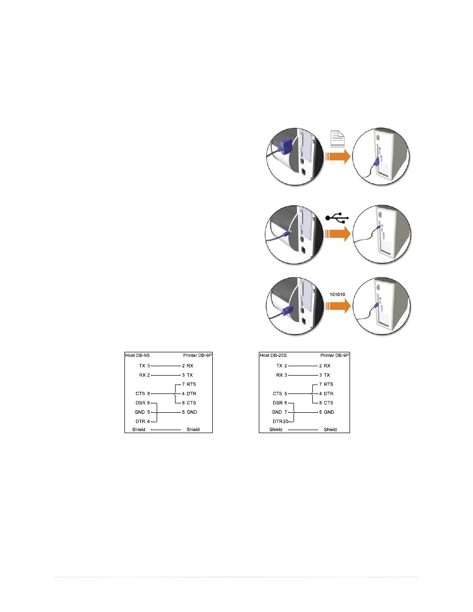
The Parallel Connection needs a Centronics
IEEE
1284 cable with a 36-pin male connector for
unidirectional (forward channel) communications, or
an IEEE 1284 Compliant cable for bi-directional
communications (forward and reverse channels).
Also, for bi-directional communications your host
must have supporting software.
The USB Connection needs a USB cable and is
supported in Windows
95 and greater operating
systems. Depending upon the operating system of
your host computer, installation requirements may
differ slightly.
The Serial Connection needs a serial interface
cable with specific pin-outs for proper
communications (part numbers and pin-outs are
given, below; contact your reseller to order). The
interface supports RS-232C communications via a
DB-9 connector. Serial port settings are menu-
selectable and must match your host’s serial port
settings.
Part # 32-2300-01
Part # 32-2301-01
SDIO and USB Host Port Connections
If equipped with the Secure Digital Input Output (SDIO) and USB Host Ports, the printer can
accept external storage devices for fonts, graphics, label formats, and firmware files. The USB
Host Port also accepts a USB keyboard for standalone, direct data (Line mode) input applications;
see the Class Series 2 Programmer’s Manual for examples.