Head pressure control valve operation ori/ord – ClimaCool IOM AR2 SERIES User Manual
Page 56
54
www.climacoolcorp.com
®
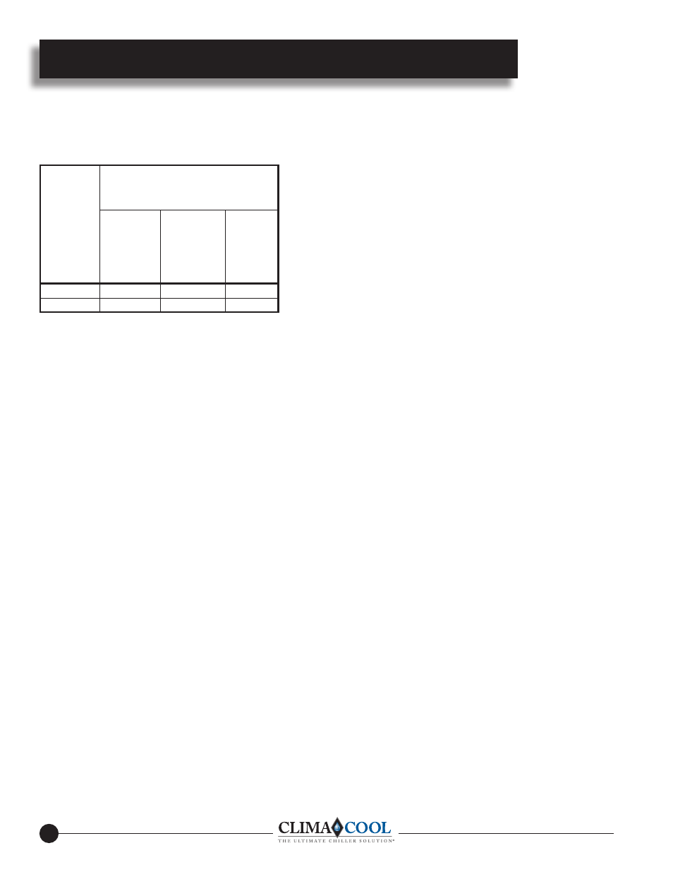
The table below lists the setting data for the ORI and ORD valves .
Other ORI settings can be obtained by adjusting the valves a
proportionate amount between those values shown .
The ORD-4-20 setting means that the ORD-4 will start to open when
the pressure difference between the discharge line and the receiver is
20 psig . This setting is suitable for all systems where the combined
pressure drop through the condenser, the ORI and connecting piping
is less than 14 psi . Therefore, if the ORI is selected for 2 psi P,
then the maximum allowable pressure drop through the condenser is
12 psi . Normally, condenser pressure drop on refrigeration systems
is less than 10 psi . However, many condensers on air conditioning
systems may have pressure drops up to 25 psi . Therefore, when
in doubt, consult with the equipment manufacturer or, if possible,
measure it by reading the discharge pressure at the compressor and
the receiver pressure during full load operation . That is, this reading
should be taken with a normal condensing temperature at full load .
For systems where the condenser pressure drop is higher than normal,
ORD valves with higher settings are available upon special request .
To adjust the ORI valve, remove the cap and turn the adjustment
screw with the proper size hex wrench (1/4” for ORI-6 and 5/16”
for ORI- 10) . A clockwise rotation increases the valve setting while
a counter-clockwise rotation decreases the setting . To obtain the
desired setting, a pressure gauge should be utilized at the compressor
discharge service valve so the effects of any adjustment can be
observed . Small adjustments are recommended to allow the system
adequate time to settle out after each adjustment . NOTE: Even though
the ORI valve is selected on the basis of the full load conditions
or summer operation, it should be adjusted to maintain the desired
condensing pressure whenever the ambient is below 70°F .
DETERMINING AMOUNT OF CHARGE — When “refrigerant
side” head pressure control is utilized on a system, one of the most
important factors is determining the total system refrigerant charge .
While on most packaged units the amount of charge is listed on the
unit, the required charge for a field built-up system cannot be listed by
the manufacturer . Charge is usually added when the system is started
up until “proper” system performance is reached . However, this is not
satisfactory and if the system is to function properly year-round, the
correct amount of extra charge must be calculated ahead of time .
1 — COMPLETELY FLOODED CONDENSER: The easiest
method is to calculate the volume of the condenser coil and then use
the density factor of the refrigerant shown in Table-1 to figure the
pounds of refrigerant necessary to completely flood the condenser
coil at the appropriate ambient . The factors involved in calculating the
extra pounds of refrigerant are:
a . Length of tubing and return bends in condenser
b . Minimum ambient temperature at which systems will be required
to function
c . Tubing size and wall thickness
d . Refrigerant
The primary point to remember in selecting the proper density factor
is that when the liquid drain valve (ORI) is throttling, the refrigerant
temperature will be at the same temperature as the ambient .
Example: Calculate the extra refrigerant charge necessary for a
Refrigerant 22, roof-top, air conditioning unit (40°F evaporator
and a minimum condensing temperature of 90°F) with compressor
unloading to 50% of full compressor capacity . To determine the
equivalent length of tubing in a condenser, proceed as follows: First,
count the number of tubes and multiply this by their length .
Example: 150 tubes x 7.55 feet = 1132.5 feet
Next, count the return bends and multiply them by the factor shown
in Table-1 .
Example: 150 bends x .250 for 1/2 inch bends = 37.5 feet Then
add this 37.5 feet to the 1132.5 feet for a total of 1170 feet
The system uses a 30 hp condensing unit with a condenser coil
containing 1170 equivalent feet of 1/2 inch tubing tubes and return
bends) . Assume a design temperature of minus 20°F minimum
ambient . From Table-1 we find the density factor necessary to
calculate the pounds of extra refrigerant to completely flood the
condenser at minus 20°F: 1170 feet x .102 pounds/foot = 119 pounds .
2 — PARTIALLY FLOODED CONDENSER:
On many systems it isn’t necessary to completely flood the condenser to
maintain sufficient operating head pressure (equivalent to approximately
90°F condensing temperature) because of a milder climate than Method
1 assumes . Therefore, a second method is available . The additional
information found in Tables 2 and 3 can be used to figure more closely
the charge necessary to properly flood the condenser for sufficient head
pressure at various minimum ambient temperatures . (The multipliers are
applied to the extra refrigerant charge that was calculated in Method 1 to
completely flood the condenser .)
Head Pressure Control Valve Operation ORI/ORD
Settings for Refrigerants
R-22 and R-407C
Valve
Type
Pressure
Setting
PSIG
Depth of
adjusting
nut from
top of
Spring
Housing
Turns
IN
from
Factory
Setting
ORI-10
200
¾”
5
ORD-4-20
20
—
—