Head pressure control valve operation ori/ord – ClimaCool IOM AR2 SERIES User Manual
Page 54
52
www.climacoolcorp.com
®
Head Pressure Control Valve Operation ORI/ORD
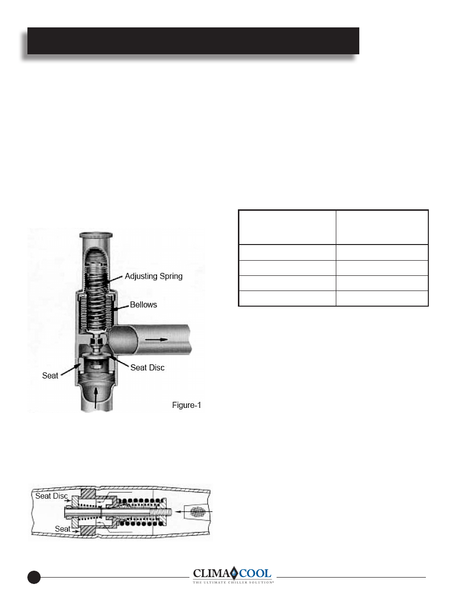
ORI VALVE OPERATION — The ORI head pressure control
valve is an inlet pressure regulating valve and responds to changes
in condensing pressure only . The valve designation stands for Opens
on Rise of Inlet pressure . As shown in Figure-1, the outlet pressure
is exerted on the underside of the bellows and on top of the seat disc .
Since the effective area of the bellows is equal to the area of the port,
the outlet pressure cancels out and the inlet pressure acting on the
bottom of the seat disc opposes the adjusting spring force . These
two forces are the operating forces of the ORI . When the outdoor
ambient temperature changes, the ORI opens or closes in response
to the change in condensing pressure . An increase in inlet pressure
above the valve setting tends to open the valve . And if the ambient
temperature drops, the condenser capacity is increased and the
condensing pressure drops off . This causes the ORI to start to close or
assume a throttling position .
ORD VALVE OPERATION— The ORD valve is a pressure
differential valve that responds to changes in the pressure difference
across the valve, Figure-3 . The valve designation stands for Opens
on Rise of Differential pressure . Therefore, the ORD is dependent
on some other control valve or action for its operation . And in this
respect, it is used with the ORI for head pressure control .
As the ORI valve starts to throttle the flow of liquid refrigerant from
the condenser, a pressure differential is created across the ORD .
When the differential reaches 20 psi, the ORD starts to open and
bypasses hot gas to the liquid drain line . As the differential increases,
the ORD opens further until its full stroke is reached at a differential
of 30 psi . Due to its function in the control of head pressure, the full
stroke can be utilized in selecting the ORD . While the capacity of the
ORD increases as the pressure differential increases, the rating point
at 30 psi is considered a satisfactory maximum value . The standard
pressure setting for the ORD is 20 psig . For systems where the
pressure drop between the compressor and the receiver is higher than
14 psi, an ORD with a higher setting is available . See Table
ADJUSTABLE ORI/ORD SYSTEM OPERATION — The
adjustable ORI head pressure control valve and the nonadjustable
ORD pressure differential valve comprise an improved system
of head pressure control . For years the usual system utilized two
adjustable or one adjustable valve with a check valve and an elevation
requirement for “refrigerant side” head pressure control . With the
introduction of the ORD-4 pressure differential valve in January 1968,
not only was the system simplified due to a one valve adjustment and
the ability to locate the condenser and receiver on the same elevation,
but the ORI/ORD system was more economical to buy . The operation
of the ORI/ORD system is such that a constant receiver pressure is
maintained for normal system operation . Since the ORI is adjustable
over a nominal range of 65 to 225 psig, the desired pressure can be
maintained for all of the commonly used Refrigerants 12, 22, and
502 . As shown in Figure-4, the ORI is located in the liquid drain line
between the condenser and the receiver . And the ORD is located in a
hot gas line bypassing the condenser . During periods of low ambient
temperature, the condensing pressure falls until it approaches the
setting of the ORI valve . The ORI then throttles, restricting the flow
of liquid from the condenser . This causes refrigerant to back up in the
condenser thus reducing the active condenser surface . This raises the
condensing pressure . Since it is really receiver pressure that needs to
be maintained, the bypass line with the ORD is required .
Maximum Pressure
Drop Between
Compressor and
Receiver (PSI)
Head Pressure
Component Selection
Below
14
ORD-20 & ORI
15 to
19
ORD-25 & ORI
20 to
24
ORD-30 & ORI
25 to
29
ORD-35 & ORI