Automatic timer flush package, Automatic timer flush (aft) package, System components – ClimaCool IOM AR2 SERIES User Manual
Page 22: Operation instructions, Control switch: (see illustration)
20
www.climacoolcorp.com
®
Automatic Timer Flush (AFT) Package
The ATF-EA-1 .5 flush valve package provides an automatic
method for flushing away the debris collected In the strainer’s
reservoir . The power supply and timer controls for the valve
package are housed inside the ATF control box . The ATF controls
can be preprogrammed to set the flushing duration and the time
interval between flushes .
System Components:
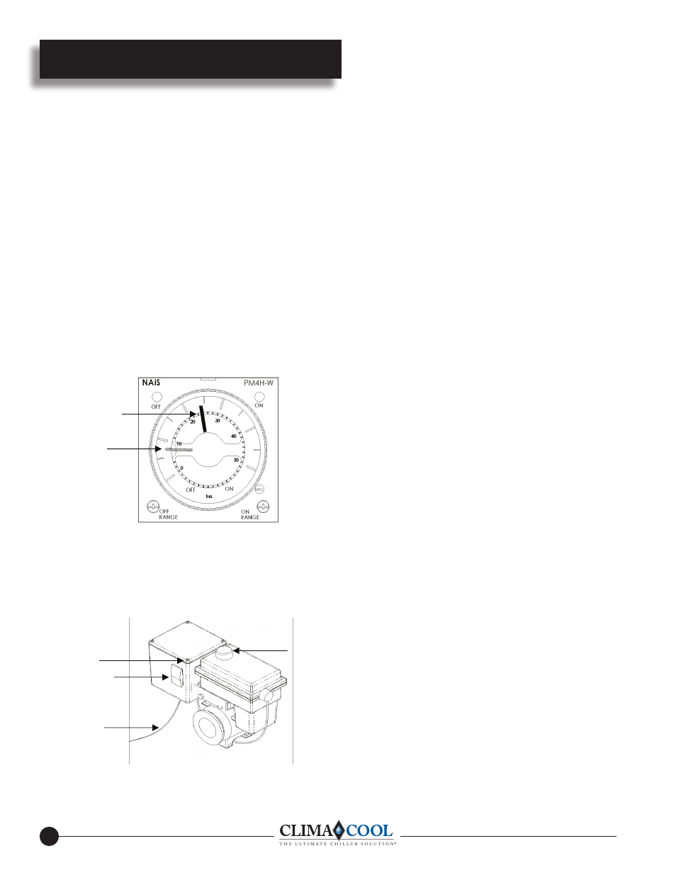
A . Timer Based Valve Controller (see Fig . 1) sets the flush
duration (length of the flush) and the flush interval (time
between flushes) .
B . Electric Ball Valve: designed for dirty water use (see Fig .
1 & 2) .
Fig . 1
A
GREEN POINTER
INNER RING
(LENGTH OF FLUSH)
(FACTORY SET AT
8-SECONDS)
RED POINTER
OUTER RING
(TIME BETWEEN
FLUSHES)
(FACTORY SET AT
24-HOURS)
Fig . 2
B
[email protected] POWER
FROM PDA OR 120V PLUG
IN TRANSFORMER
OPEN/CLOSE
INDICATOR
COVER-PLATE SCREWS
(4) IN CORNERS OF BOX
(TIMER BASED VALVE
CONTROLLER)
CONTROL SWITCH
Automatic Timer Flush Package
Operation Instructions:
Flush valve line must be piped to atmospheric pressure such as an
open floor drain . The flush line should not undergo any changes
in elevation and should be sloped downward in the direction of
drainage . DO NOT PIPE THE FLUSH OR DRAIN LINE INTO
A PRESSURIZED LINE .
Note: The Automatic Timer Flush Package Needs To Be
Programmed When It Is Received By The End-user . The
programming is simple and takes only a few moments . However,
because every application has different parameters that affect the
required frequency between flushes and the duration of the flush,
the end-user must choose the controller’s settings (refer to your
specific strainer manual) .
To program the ATF Controller:
Plug the transformer into a 120-VAC outlet . Insert the 12-VDC
plug coming from the transformer into the jack on the underside
of the ATF box . Test for power by pressing the manual flush side
of the control switch (lower switch light should come on and the
valve will start to open) . Adjust the “ON-TIME” (Valve Open)
by turning the inner timer ring with the GREEN POINTER
clockwise to increase duration . (“ON-TIME” RANGE, See Fig .
1) Adjust the “OFF-TIME” (Valve Close) by turning the outer
ring with the RED POINTER clockwise to increase duration .
(“OFF-TIME” RANGE, See Fig . 1) Set the control switch to auto
flush . The red off light on the timer will come on and the upper
light on the switch will come on and stay on . During the flush
cycle the on light on the timer and the lower switch light will
come on .
Control Switch: (see illustration)
Control switch flushing is initiated by pressing and holding
down the manual control switch located on the front of the
controller . The manual flush control switch can also be used to
conveniently drain the water out of the strainer before removing
the conical screen element from the strainer housing . A yellow
indicator arrow on top of the ATF Valve will rotate in sync
with the ball valve to show the valve position (open or closed) .
When the manual flush control switch is released, the valve will
automatically close .\