Site preperation/installation – ClimaCool IOM AR2 SERIES User Manual
Page 5
3
www.climacoolcorp.com
®
Site Preperation/Installation
SITE PREPARATION
Base Requirements
The minimum base requirement for the ClimaCool chiller is a
level surface which has been checked to ensure that it is capable
of bearing the combined operating weight of the modules (see
page 4) .
Anti-Vibration Mountings
Although the compressors are installed on anti-vibration
mountings, further isolation of the chiller from the structure can
be achieved by installing vibration-eliminating springs or pads
under the base rails on which the chiller will rest . (see page 8 -
Vibration Isolation) .
Service Access
The minimum space required for electrical panel service is 36”
in the front of each module . Allow 24” service clearance in the
back of the module for refrigeration access . Allow a minimum
of 18” of clearance above the module for service . Allow 12” side
clearance of any ClimaCool modular chiller system (see Service
Clearances page 7) . Local building or electrical codes may
require additional clearance .
Draining
When performing standard maintenance procedures such as
flushing heat exchanger, it will be necessary to close off a section
of a module . ClimaCool modular chillers come equipped with
isolation valves for this purpose . Access to a floor drain is helpful
when performing standard maintenance procedures .
INSTALLATION
Assembling Modules
Use of (2) 4” rails (minimum size) is required for ease of
installation . One of the end modules should be chosen as the
reference module and carefully located .
A factory supplied fastener kit is provided for the adjoining
of each module . Each kit contains (2) gaskets, (16) ¾” fully
threaded studs, (32) heavy duty hex nuts, (32) lock washers, and
(32) flat washers .
A ¾”-10 tap should be run through each weld nut located at the
bottom rear chiller header flange of each module . Screw the fully
threaded studs into these four weld nut locations . At all other
flange hole locations, insert fully threaded studs, attach washers,
lock washers, and nuts from the fastener kit .
The gasket should be placed between the first reference module
and the next module . Slide the next module into position while
guiding the fully threaded studs into the flange holes of the next
module . Finally, the washers, lock washers, and nuts are applied
to the other end of the fully threaded studs to securely fasten the
module flanges .
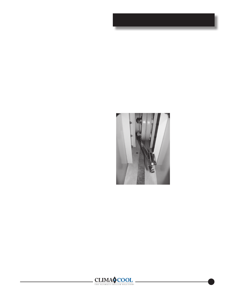
Tighten the flange bolts in a diametrically opposite pattern,
in such a way as to pull the modules together evenly . It will
be necessary to use a ¾” (12 point) box-end wrench when
tightening . As each module is added, the alignment of the whole
package should be confirmed .
Header and Flange Insulation
Chilled water piping is pre-insulated on each module at the
factory with ¾” closed cell foam rubber . After the bolting the
modules together, the installer must apply insulation on site over
the chilled water header connection flanges .
Connecting the Water Piping to Modules
Water piping must be installed in accordance with applicable
codes and standards . Flexible connections and supports should
be installed to prevent load or stress on the module’s flange
connections (see page 11 - Water Piping Configurations) .