4 - controls and components – CEMB USA C68SE (B) User Manual
Page 7
I 0201 GB- 7
4 - CONTROLS AND COMPONENTS
4.1 - BRAKE PEDAL
This pedal allows the operator to hold
the wheel when fi tting the counterwei-
ghts. It must not be actuated during
the measuring cycle.
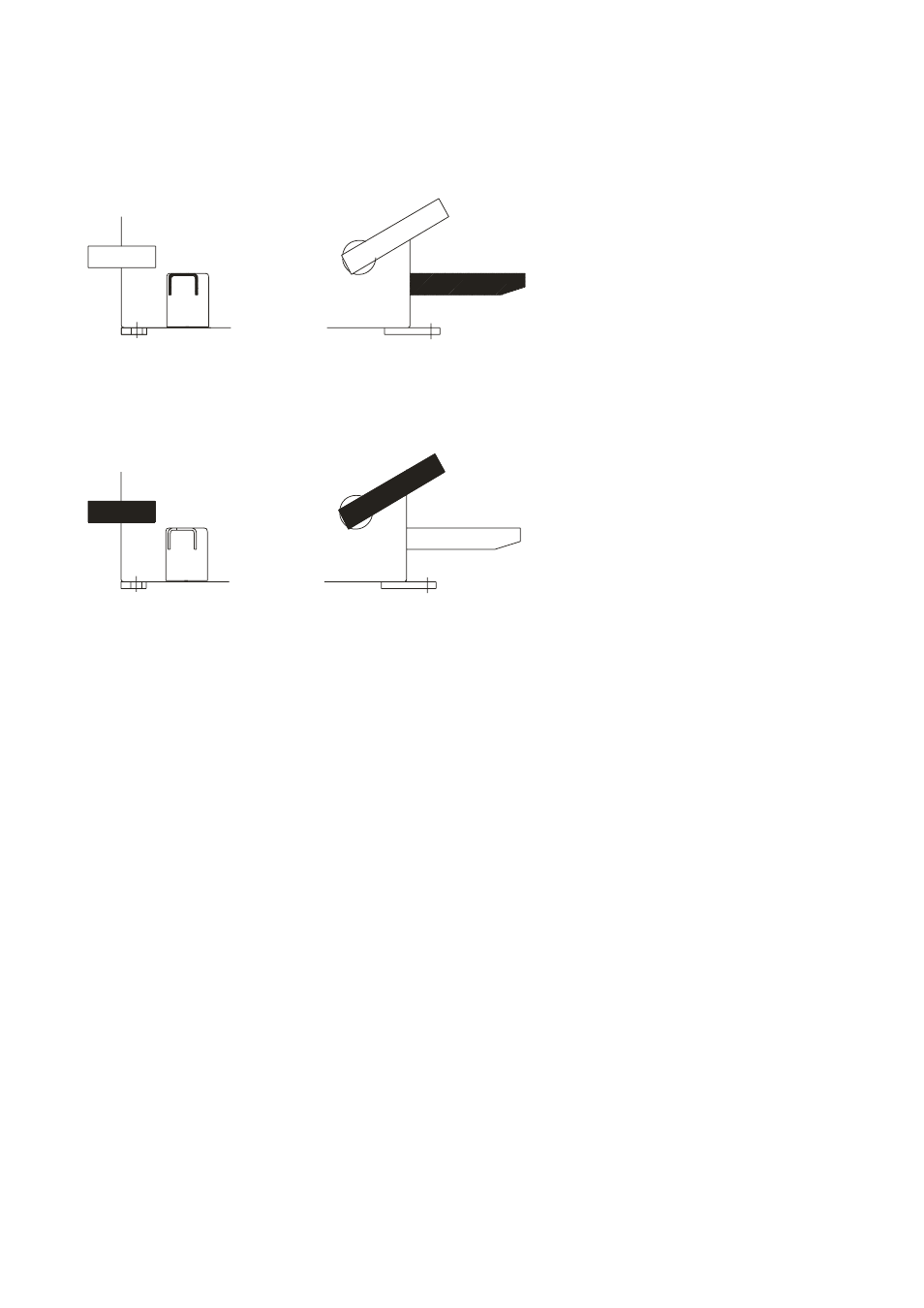
4.2 - PNEUMATIC LOCKING PEDAL
This pedal allows releasing the
device fastening the wheel on the
adapter. Do not actuate this pedal
during the machine cycle and/or
when adapters other than the
standard cone adapter are moun-
ted.
The pedal has a stable position; UP
to clamp the wheel, held DOWN to
release it.
4.3 - AUTOMATIC DISTANCE AND DIAMETER GAUGE
This gauge allows measurement of the distance of the wheel from the machine and the wheel diameter at
the point of application of the counterweight.
It also allows correct positioning of the counterweights on the inside rim by using the specifi c function (see
Indication of exact correction weight position
) which allows reading, on the monitor, the position used
for the measurement within the rim (For calibration, see Calibration).
The gauge can only be used with the counterweight pincers mounted.
4.4 - AUTOMATIC WIDTH GAUGE (Option)
Width gauging is through a SONAR device which measures the distance of the wheel without mechanical
contact, merely by closing the guard and each time a valid measurement has been made with gauge 4.3.
4.5 - COUNTERWEIGHT DISPENSER (Option)
The dispenser consists of a mechanism, controlled by the measuring instruments, designed to distribute
a counterweight equivalent to the measured weight, thus avoiding the approximations of commercial
counterweights. The counterweight is cut to the exact weight even if the approximate weight appears
on the displays. Accuracy of the weight is ± 1 gram. To dispense the counterweight, press relative
function push button for each side. The dispenser is operated pneumatically and uses the max. inlet
pressure which should be at least 7 kg/cm
2
.
4.6 - AUTOMATIC WHEEL POSITIONING
At the end of the spin, the wheel is positioned according to the unbalance on the outside or else
according to the static unbalance (when selected).
Accuracy is ± 20 degrees.
4.7 - CLOCK CONTROL
The wheel balancer is provided with a clock having a back-up of about one month with the machine
switched off. If the machine remains off for a long period, at the fi rst switch on, check the date and time
(see Clock set-up), adjusting them if necessary.