5 result of measurement – CEMB USA C68SE (B) User Manual
Page 16
I 0201 GB - 16
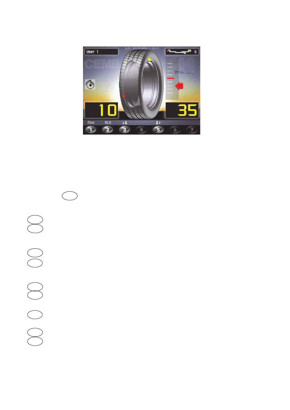
5.5 RESULT OF MEASUREMENT
After performing a balancing spin, the unbalance values are displayed as well as arrows useful for
positioning the point of application of the correction weight. After positioning the wheel, apply the weight
in the 12 o’clock position. When the beep signal is enabled (see section ACUSTIC SIGNAL), reaching of
the correction position is accompanied by a “beep”.
If the unbalance is less than the chosen threshold value, the “OK” appears instead of the unbalance value
to indicate, on that particular side, the wheel is in tolerance; the residual unbalance can be displayed by
pressing button
1
with an accuracy of 0.5 g (0.1 oz).
The following buttons are enabled:
1
Display of residual unbalance
2
Selection of correction mode (DYNAMIC, STATIC, ALU1, ALU2, ALU3, ALU4, CTS).
When the mode is changed, the unbalance values are recalculated automatically on the
basis of the previous spin (ALU AND STATIC MODES).
3
The weight to be applied on the inside is distributed by the dispenser.
4
Eccentricity measurement graph (option). The symbol above the key turns red is fi rst
harmonic eccentricity exceeds the limit indicated by the setup parameters (see
FIRST HARMONIC LIMIT).
5
The weight to be applied on the outside is distributed by the dispenser.
6
Split control for splitting of unbalance over presettable components (“SPLIT” CON
TROL). Button only enabled in STATIC or ALU S correction.
7
Indication of the longitudinal position of the unbalance (INDICATION OF EXACT COR
RECTION WEIGHT POSITION.) is enabled
MENU'
For selection of special functions
START
Balancing
spin.
N.B. If the machine remains on this screen without being used for more than the time preset in the Setup
parameters (6), the screen automatically returns to the screen-save.