0 jackscrew override, Series 98 operation & maintenance – Bray 98 Series User Manual
Page 31
All information herein is proprietary and confidential and may not be copied or reproduced without the expressed written consent of
BRAY INTERNATIONAL, Inc. The technical data herein is for general information only. Product suitability should be based solely upon customer’s
detailed knowledge and experience with their application.
S98 O & M : 31
Series 98 Operation & Maintenance
16.0 Jackscrew Override
Jackscrews provide an economical manual override option on the
actuator for use in case of air failure. These jackscrews come in
two types, direct hand wheel operated and bevel gearbox driven.
The direct hand wheel jackscrew has a rotating screw threading
into a bronze nut when installed on the Torque module of DA
actuators and on the Spring module of Spring Return actuators.
The hand wheel directly turns the screw or nut to move the
jackscrew forward or back.
The bevel gearbox driven jackscrews are required to reduce the
manual effort on larger actuator models and stiffer springs that
require higher thrust to compress. Here the screw translates with
an anti-rotation arrangement.
16.1 Installation
Jackscrew overrides are usually factory installed on the actuator.
Override units are shipped with the jackscrew assembly installed
on the actuator so that the actuator is ready for installation in
the auto operation mode. No additional customer installation is
required.
If a field retrofit is required on actuators without a manual over-
ride, the installation instructions provide a guide for a qualified
technician to install and operate the Jackscrew overrides.
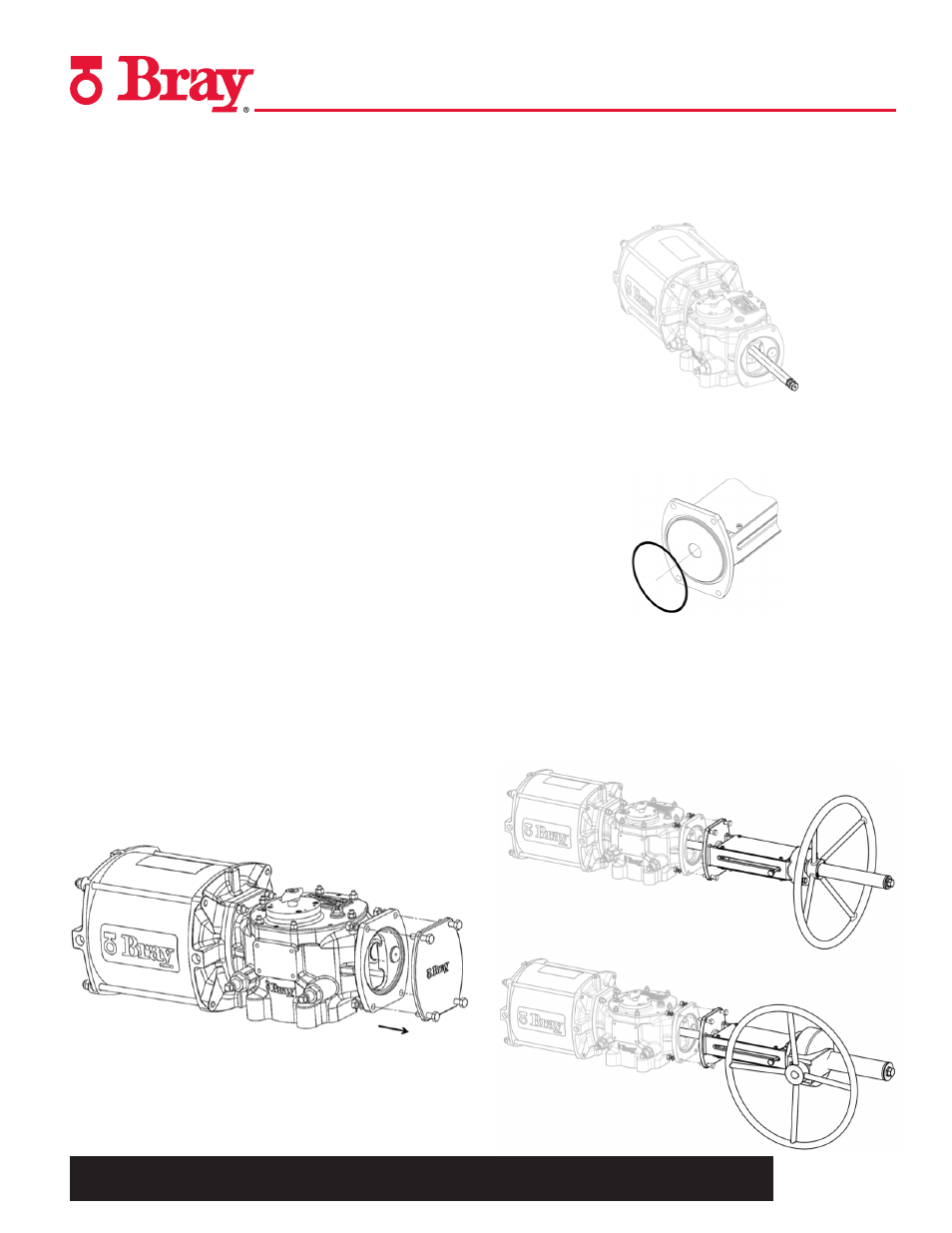
16.1.1 Installing DA Jackscrew Override
1. Disconnect the air pressure and the electrical power from
actuator.
2. Remove the DA end cover plate from the actuator.
3. Free the Extension Rod from the Jackscrew assembly, apply
a drop of medium strength thread lock compound on the
extension rod threads and firmly tighten it into the threading
in the Guide Block inside the Torque Module.
4. Coat the extension rod with NLGI2 grease.
5. Lubricate and place the flange O-ring into the groove on the
jackscrew assembly flange
6. Back off the jackscrew fully in the assembly and carefully
slide the mounting flange of the jackscrew assembly on the
extension rod. Take care in locating the bushing and the
flange seal on the extension rod.
7. Slide the assembly to locate and mate the flanges. Use the
hardware supplied in the kit to fasten the assembly to the
Torque Module flange.
Direct Drive Ja
ckscrew -DA
Gear Drive Ja
ckscrew -DA