Series 98 operation & maintenance, 2 operation - spring return hydraulic override, 2 installing hydraulic override on da actuator – Bray 98 Series User Manual
Page 28
All information herein is proprietary and confidential and may not be copied or reproduced without the expressed written consent of
BRAY INTERNATIONAL, Inc. The technical data herein is for general information only. Product suitability should be based solely upon customer’s
detailed knowledge and experience with their application.
S98 O & M : 28
Series 98 Operation & Maintenance
MOP for SR Hydraulic Overrides
Model
MOP
Spring Number
1
2
3
4
5
73 E2
psi
1730
2045
2630
2980
bar
119
141
181
205
14 E3
psi
1445
1660
1930
2460
2930
bar
100
114
133
170
202
24 E3
psi
1400
1670
2125
2450
2815
bar
97
115
147
169
194
45 E3
psi
1290
1535
1765
2020
2340
bar
89
106
122
139
161
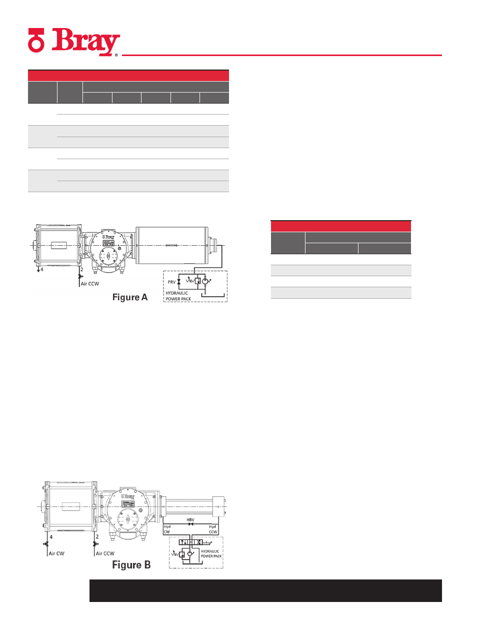
15.1.2 Operation - Spring Return Hydraulic
Override
1. To operate the override, turn the 3/2 way valve on the pressure
module to vent the cylinder port to atmosphere and Close
the pressure release valve (PRV) on the hand pump manifold.
Operating the Hand Pump on the power pack extends the
ram, pushes the Spring Rod while compressing the spring
and operates the actuator manually.
2. Opening the pressure release valve relieves the hydraulic
pressure to reservoir. The spring returns the ram of override
cylinder to retracted position and the actuator to fail safe
position.
3. To restore normal Automatic operation, turn the pressure
release valve to full Open and switch the 3/2 way valve on
pneumatic cylinder, to connect the cylinder port to the air
supply pressure.
15.2 Installing Hydraulic Override on DA Actuator
1. Turn the actuator so that the guide block is at the cover end
side of the Torque Module and ensure it stays in this position
after disconnecting air pressure and electrical power from
actuator.
2. Remove the DA cover plate from the torque module and
mount the DA hydraulic override cylinder assembly with the
hardware supplied in mounting kit. Make sure to install the
flange O-ring.
3. Remove the end cap of the hydraulic cylinder. With a suitable
socket/tube spanner located on the hex head of the hydraulic
piston end, thread and tighten the piston rod into the
threading on Guide Block inside the Torque Module. Refer
to the table below for tightening torque.
Piston Rod Tightening Torque
Model
Torque
Lb-ft
Nm
73 E2
110
150
14 E3
130
180
24 E3
130
180
45 E3
150
200
4. Replace the end cap, taking care not to damage the cap seal,
and tighten the tie rod nuts of the hydraulic cylinder.
5. Install the 3-way valves, rated for 150 psi (10.3 bar) working
pressure, on the pneumatic cylinder ports (Refer to Figure B)
and turn them to venting position.
6. Mount the hydraulic pump assembly on the Torque Module’s
rear accessories pad, as described in previous section.
7. Tube the ports of the hydraulic cylinder to the direction
control valve’s ports, on the hydraulic hand pump unit.
(Refer to Figure B)
8. Turn the direction control valve on the hand pump unit
to direct oil flow to one of the cylinder ports. Loosen the
corresponding vent plug on the cylinder and stroke the hand
pump to vent out air in the lines. Tighten the vent plug when
no more air bubbles are seen. Repeat the same for the other
side of the cylinder.
9. Check and ensure the Hydraulic pressure setting of the pump
does not exceed the MOP setting, refer to the table on page
27. Use the plugged port on the pressure line Tee to connect
a suitable pressure gage.