0 hydraulic override, Series 98 operation & maintenance – Bray 98 Series User Manual
Page 27
All information herein is proprietary and confidential and may not be copied or reproduced without the expressed written consent of
BRAY INTERNATIONAL, Inc. The technical data herein is for general information only. Product suitability should be based solely upon customer’s
detailed knowledge and experience with their application.
S98 O & M : 27
Series 98 Operation & Maintenance
15.0 Hydraulic Override
Hydraulic overrides on S98 actuators provide low effort, high
thrust in a compact size for manually operating the actuator.
The hydraulic override cylinders are single acting on the SR
models and double acting on the DA models of the Actuators.
These are available on Models 73E2 through 45E3.
The hydraulic override consists of a power pack with a hand
operated high pressure pump and oil reservoir connected by
tubing to the hydraulic override cylinder. The hydraulic cylinder
is mounted on the Spring Module end thrust base on SR models
and on the Torque Module flange on the DA models.
The hydraulic override cylinders are designed for 3,000 psi max
working pressure and provide adequate thrust to output the
required valve torque. The operating pressure required is set on
the hand pump assembly through a built-in relief valve.
15.1 Installation
Series 98 standard actuators with hydraulic overrides are shipped
pre-assembled with the cylinder, hand pump, bypass valves and
tubing complete. The hand pump unit is selected, factory installed
and the hydraulic pressure valve set per the application. No addi-
tional customer installation/adjustment is usually required.
Actuators in service, without this override option, can be retrofit-
ted with the override kit as described below.
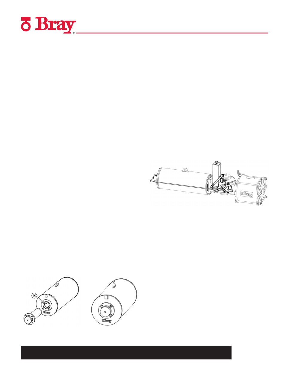
15.1.1 Installing Hydraulic Override on Spring
Return Actuators
1. Disconnect air pressure and electrical power from actuator.
2. In fail safe position of the actuator, remove the end cover
plate retaining the O-ring on the Spring Module end.
3. Firmly thread the studs (10) supplied with the override
mounting kit, into the thrust base. With the ram fully
retracted, insert the Hydraulic Cylinder into the Spring
Module mating the cylinder flange to the thrust base while
positioning the air venting plug at the top.
4. Secure the cylinder flange on the thrust base of the Spring
Module with the spring washers and nuts from the override
mounting kit.
5. Thread in the hydraulic connector into the cylinder port
(if not already fitted into the cylinder). Use a commercial
hydraulic fitting thread sealant (Loctite 542 or equivalent).
6. Fit a 3-way valve, rated for 150 psi (10.3 bar) working
pressure, to the pneumatic module’s port (Refer to Figure A
on page 26).Turn the valve to venting position so that the
pneumatic cylinder’s port is connected to atmosphere.
7. Fit the hydraulic hand pump assembly bracket on the rear
accessories mounting pad of the Torque Module with the 4
bolts supplied in the kit. Tube the cylinder port to the pump
outlet port, as in Figure A. The standard mounting, as shown,
is for the actuator in horizontal orientation. Special brackets for
other orientations of the actuator can be supplied upon request.
8. On the Tee at the pump outlet, remove the plug and install a
suitable pressure gage (0-4000psi).
9. Fill the hand pump reservoir to the required level with
hydraulic fluid (ISO 32 grade for general application). Install
the breather cap on the reservoir (do not substitute the
breather cap with a plug). Stroke the pump a few times with
the pressure release valve on the pump open to bleed air out
of pump.
10. Lightly loosen the air vent screw on the cylinder flange to
bleed off air from the hydraulic lines. Close the pressure
release valve on the pump and stroke the hydraulic pump till
the pressure builds up. Tighten the vent plug when no more
air bubbles bleed out. The ram advances to press against
the Spring Rod’s end face and the thrust from the hydraulic
cylinder ram effects the override function.
11. Note the maximum hydraulic pressure setting for the
actuator model (refer to the MOP table on page 26). Check
the hydraulic pressure on the gage at the end of the actuator’s
stroke. Refer to the hand pump service manual and adjust
the overload valve setting on the pump to the MOP.