Trigger operation, Remote inhibit (ri) - input – B&K Precision 9150-9153 - Manual User Manual
Page 18
18
TRIGGER:
Pins 1 and 2 can be used to apply external trigger sources to the power supply. These pins can
also be used to control the list operation
RI/DFI:
The Inhibit Input pin can be used to control the output state of the power supply (RI function).
The Fault Output pin (DFI function) can be used to indicate internal faults of the power supply.
NOTE: The Fault indicator function (DFI) is only available for models 9120A, 9121A, 9122A, 9123A, and
9124.
DIGITAL I/O: Read and control output and input state of the 2 available pins. For models 9150, 9151, 9152,
and 9153, only digital input is available.
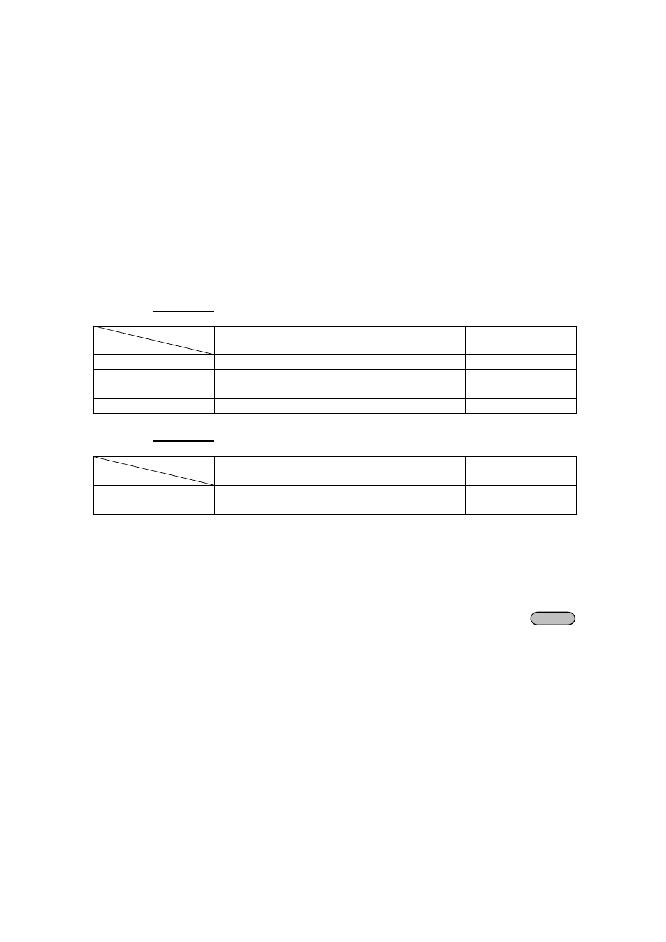
For Models: 9120A, 9121A, 9122A, 9123A, 9124
Mode
Pin
Trigger
RI/DFI
DIGITAL I/O
1 (INH)
Trigger in
Inhibit Input
Digital Input
2 (GND)
GND
GND
GND
3 (FLT)
Not Used
Fault Indicator Output
Digital Output
4 (GND)
Not Used
GND
GND
For Models: 9150, 9151, 9152, 9153
Mode
Pin
Trigger
RI
DIGITAL I/O
1 (TRIN)
Trigger in
Inhibit Input
Digital Input
2 (GND)
GND
GND
GND
Trigger Operation
The power supply supports 3 different trigger modes. Immediate, External and Bus. Configure one of the trigger
sources before performing trigger operation.
• Trigger Key:
When this function is enabled, you can generate an immediate trigger pulse by pressing
Shift
Trigger.
• External trigger signal (TTL):
When this function is enabled, the power supply can be triggered with a TTL pulse applied to pin 1 of
the terminal connector in the rear. The TTL on pulse width should be at least 5 ms.
• Bus:
When this function is enabled, you can trigger the power supply by sending a *TRG or TRIgger
command to the power supply
Remote Inhibit (RI) - Input
Used to turn off the output of the power supply. Can be used to turn off several power supplies simultaneously.