Atec Rohde-Schwarz-ZVA Series User Manual
Page 34
Version 10.00, May 2012
34
Rohde & Schwarz
R&S
®
ZVA Vector Network Analyzer
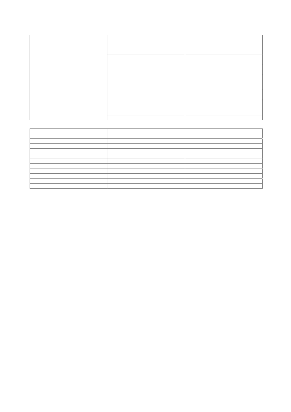
Noise level
R&S
®
ZVA8
300 kHz to 8 GHz
is increased by 1 dB
R&S
®
ZVA24
10 MHz to 13 GHz
is increased by 1 dB
13 GHz to 24 GHz
is increased by 2 dB
R&S
®
ZVA40
10 MHz to 13 GHz
is increased by 1 dB
13 GHz to 24 GHz
is increased by 2 dB
24 GHz to 40 GHz
is increased by 3 dB
R&S
®
ZVA50
10 MHz to 13 GHz
is increased by 1 dB
13 GHz to 24 GHz
is increased by 2 dB
24 GHz to 50 GHz
is increased by 3 dB
R&S
®
ZVA67
10 MHz to 13 GHz
is increased by 1 dB
13 GHz to 24 GHz
is increased by 2 dB
24 GHz to 67 GHz
is increased by 3 dB
Universal control interface I/O port
several control and trigger signals, 36-pin Centronics connector, 3.3 V TTL
for controlling external devices, limit checks, sweep signals, etc.
Agilent handler interface compatibility
type 3
Input signals
pin 2, pin 18
3.3 V TTL, 5 V tolerant
Output signals
pin 3 to pin 17, pin 19 to pin 21,
pin 30 to pin 34, pin 36
3.3 V TTL, 5 V tolerant
Input/output signals
pin 22 to pin 29
3.3 V TTL, 5 V tolerant
+5 V output
pin 35
+5 V, max. 100 mA
Response time of write strobe signal
pin 32
1 µs
Pulse width of write strobe signal
pin 32
1 µs
Pulse width of external trigger signal
pin 18
> 1 µs
Pulse width of sweep end signal
pin 34
> 10 µs