Atec Agilent-E5071C User Manual
Page 59
59
Option 230/235/240/245/260/265/280/285/430/435/440/445/
460/465/480/485
Table 62.
Corrected system performance with type-N 75 Ω device connectors,
85036E calibration kit
Network analyzer:
E5071C
calibration kit:
85036E (type-N 75 Ω)
50 to 75 Ω adapters:
11852B
calibration:
full
2-port
IF bandwidth = 10 Hz, no averaging applied to data, environmental temperature = 23 °C
±5 °C with < 1 °C deviation from calibration temperature, isolation calibration performed
Typical
(dB)
Description
10 MHz to 3 GHz
Directivity
37
Source match
33
Load match
39
Reflection
tracking
±0.015
Transmission tracking
±0.019
10 MHz to 3 GHz
S11 = S22 = 0; Source power = –10 dBm
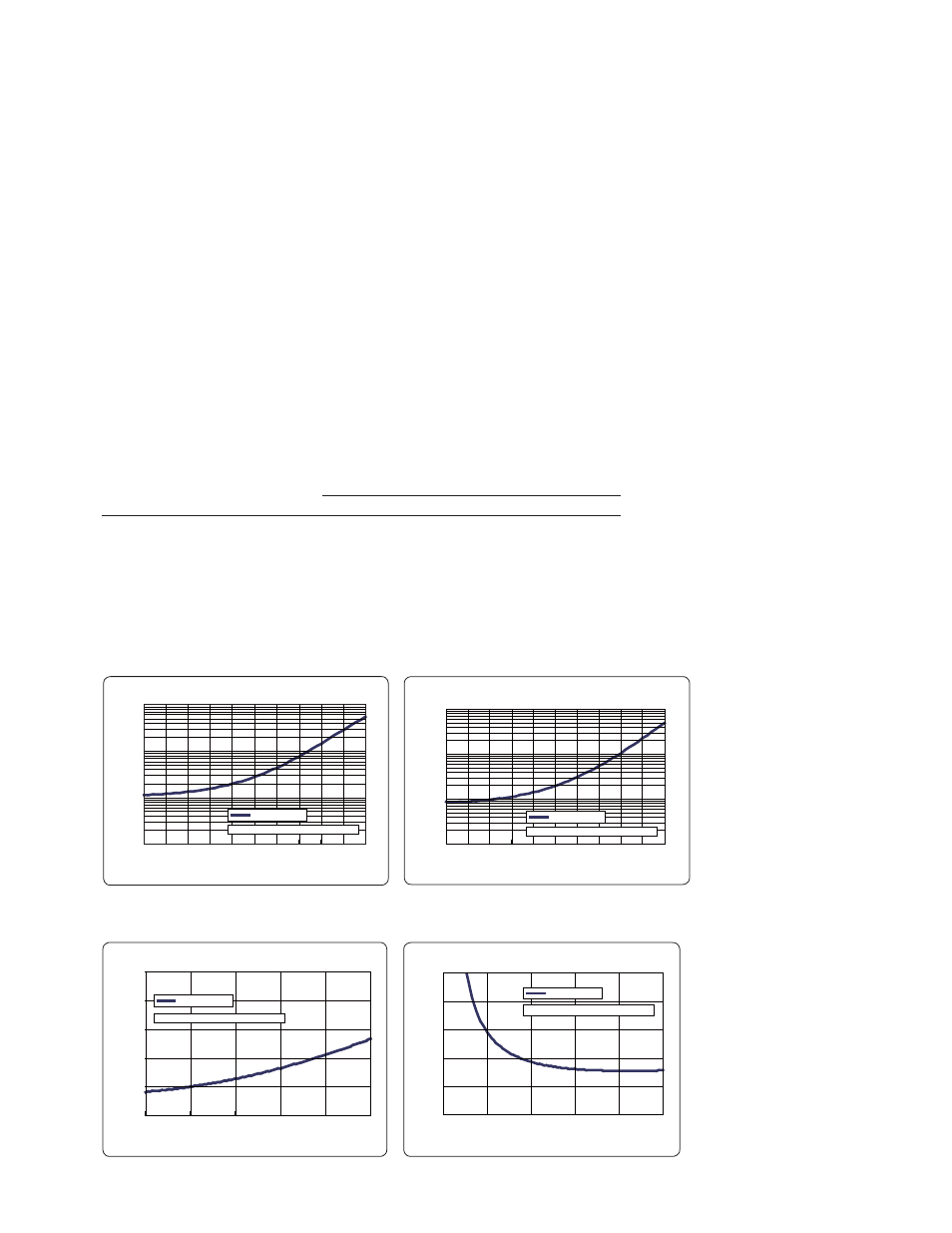
Transmission using 85036E and 11852B
Transmission coefficient (dB)
10
1
0.1
0.01
Mag (dB)
10 0 –10 –20 –30 –40 –50 –60 –70 –80 –90
10 MHz to 3 GHz
S11 = S22 = 0; Source power = –10 dBm
Transmission using 85036E and 11852B
Transmission coefficient (dB)
100
10
1
0.1
Phase (deg)
10 0 –10
–20
–30
–40
–50
–60
–70
–80
–90
10 MHz to 3 GHz
S21 = S12 = 0; Source power = –10 dBm
Reflection using 85036E and 11852B
Reflection coefficient (linear)
10
8
6
4
2
0
Phase (deg)
0 0.2 0.4
0.6 0.8 1
10 MHz to 3 GHz
S21 = S12 = 0; Source power = –10 dBm
Reflection using 85036E and 11852B
Reflection coefficient (linear)
0.1
0.08
0.06
0.04
0.02
0
Mag (linear)
0 0.2 0.4 0.6 0.8 1
Transmission uncertainty 10 MHz to 3 GHz (typical)
Reflection uncertainty 10 MHz to 3 GHz (typical)
Magnitude
Phase
Magnitude
Phase
Corrected System Performance for 75 Ω Measurements with 11852B
50 to 75 Ω Minimum-Loss Pads (Supplemental Information)