Atec Agilent-85133F User Manual
Page 82
82
Installation and User’s Guide
2
Installing the System
Agilent 4156C Systems with Agilent 41501B Expander Box
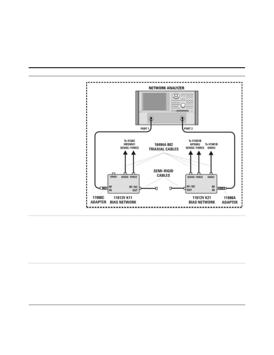
To connect the bias networks
Step
Action
Notes
1 For Agilent 4156C with
41501B expander box
systems, refer to the
following figure.
2 Connect the triaxial
cables from the 4156C to
the bias networks.
a Connect the triaxial cables from the 4156C
HRSMU1 FORCE and SENSE connectors to
the DC FORCE and DC SENSE connectors
on the port 1 bias network.
b Connect the triaxial cables from the 41501B
HPSMU FORCE and SENSE connectors to
the DC FORCE and DC SENSE connectors
on the port 2 bias network.
•
From the rear of the system, route the
cable through the feedthrough panel.
•
The port 1 bias network is the 11612V
K11.
•
The port 2 bias network is the 11612V
K21.
•
3 Connect and route the
triaxial cable from 4156C
HRSMU3 FORCE
connector to the port 2
bias network.
a From the rear of the system, connect one
end of the triaxial cable to the GNDU
connector on the 41501B rear panel.
b From the rear of the system, route the cable
through the upper feedthrough panel.
c Connect the triaxial cable to the port 2 bias
network GNDU connector.
•
The triaxial cable model number is
16494A Option 002.
•
Leave the GNDU connector on the port
1 bias network open.
•