Atec Agilent-8510C User Manual
Page 25
25
Verification kits
Verification kits are used to verify that a network
analyzer is operating within its specified performance.
Agilent Technologies offers verification kits that include
precision airlines, mismatch airlines, and precision fixed
attenuators. All verification kits include measurement
data and uncertainties which are traceable to the U.S.
National Institute of Standards and Technology (NIST).
Verification kits
Verification Connector Frequency
Description
kit
type
range (GHz) (Contents)
85051B
7 mm
0.045–18
10 cm airline, stepped
impedance airline, 20 dB, and
50 dB attenuators
85053B
3.5 mm
0.045–26.5
7.5 cm airline, stepped
impedance airline 20 dB, and
40 dB attenuators
85055A
Type-N
0.045–18
10 cm airline, stepped
impedance airline, 20 dB and
50 dB attenuators
85057B
2.4 mm
0.045–50
50
Ω airline, stepped
impedance airline, 20 dB and
40 dB attenuators
R11645A
WR-28
26.5–40
All contain:
Q11645A
WR-22
33–50
Standard waveguide section
U11645A
WR-19
40–60
Standard waveguide
mismatch
V11645A
WR-15
50–75
20 dB attenuator
W11645A
WR-10
75–110
50 dB attenuator
Test port return cables
Test port cables are available in the 7 mm, 3.5 mm,
Type-N, 2.4 mm, and 1.0 mm connector types
1
. The
configurations and performance for all cables are
described in the tables on the opposite page. All cable
ends connect directly to the special rugged test port of
the network analyzer test set.
Agilent offers two cable designs: semi-rigid and flexible.
Semi-rigid cables offer excellent performance and are
suitable for applications where the connectors of the DUT
are “in-line” or parallel. Flexible cables are ideal for manu-
facturing environments since they are more rugged and
have a tighter bending radius than semi-rigid cables.
Semi-rigid cables are warranted for 90 days;
flexible cables are warranted for one year.
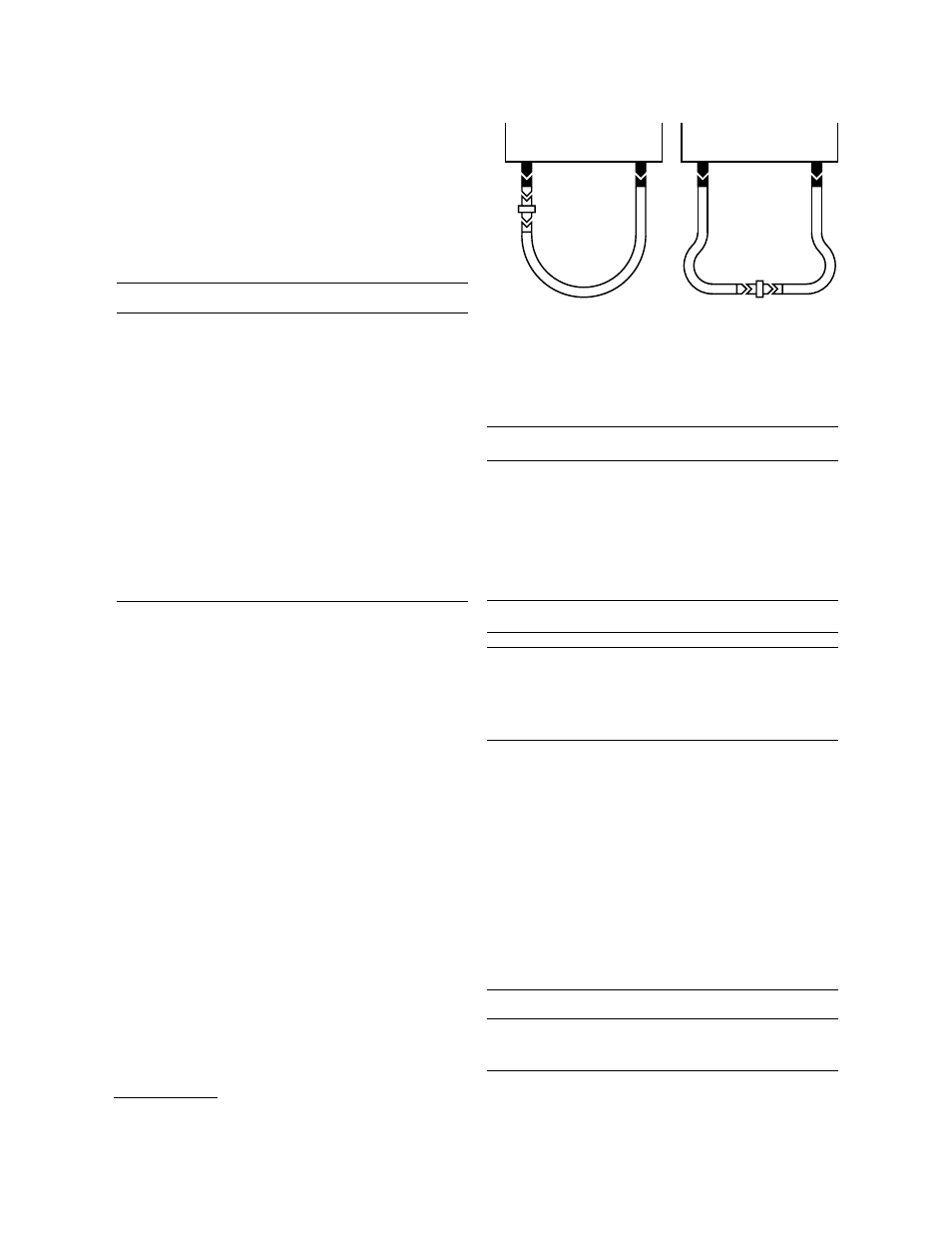
Either a single long cable or a shorter cable set can
connect a coaxial device to the test set. A single cable
with an appropriate test port adapter is best for applica-
tions where the DUT requires a connection next to the
test port for mechanical rigidity. A set of cables offers the
flexibility required to position the test devices away from
the test set.
Test port adapter sets
The 85130 series test port adapter sets protect the test
set port when connecting devices to the test port. These
adapters convert the rugged test set port to a
connection that can be mated with the device under test.
Each set contains a male and a female adapter.
Adapter sets
Adapter Connector type
Frequency Return loss
set (test port to device)
(DC–f
max
)
(dB) @ f
max
85130C
3.5 mm
2
to Type-N
DC–18 GHz
≥28
85130D
3.5 mm
2
to PSC-3.5 mm (f) DC–26.5 GHz
≥28
or 3.5 mm (m)
85130E
2.4 mm
2
to 7 mm
DC–18 GHz
≥26
85130F
2.4 mm
2
to PSC-3.5 mm (f) DC–26.5 GHz
≥26
or 3.5 mm (m)
85130G
2.4 mm
2
to PSC-2.4 mm (f) DC–50 GHz
≥23
or 2.4 mm (m)
11904S
2.4 mm
2
to 2.92 mm (4)
DC–40 GHz
≥28
Waveguide to 1.0 mm adapter kits
Adapter kit
Frequency range Description (contents)
V85104A K10
DC–75 GHz
WR-15 to 1.0 mm (f)
adapters (4) and 1.0 mm
coax cables (2)
W85104A K10
DC–110 GHz
WR-10 to 1.0 mm (f)
adapters (4) and 1.0 mm
coax cables (2)
85043C racked system kit
85043C racked system kit is a rack standing 132 cm
(52 in) high, with a width of 60 cm (23.6 in), and a depth
of 80 cm (32 in). Complete with support rails and AC power
distribution (suitable for 50 to 60 Hz, 100 to 240 VAC),
the kit includes rack mounting hardware for all instru-
ments. Thermal design is such that no rack fan is needed.
Bias networks
The 11612 bias networks apply DC as close to the device
as possible, bypassing the test set's internal shunt resistor.
These bias networks are especially useful when measuring
DC parameters of semiconductor devices.
Maximum
Maximum
Model number
Frequency range
current
voltage
11612A K10/K20
3
45 MHz–26.5 GHz
0.5 amps
40 volts
11612A K12/K22
3
400 MHz–26.5 GHz
2.0 amps
40 volts
11612B K11/K21
3
45 MHz–50 GHz
0.5 amps
40 volts
Network analyzer
test set
Network analyzer
test set
Test port
adapter
Device
under
test
Single cable
Device
under
test
Cable set
1.
To measure Type-N devices, use a pair of 7 mm cables and the 7 mm-to-Type-N adapters provided in the
85054B, D calibration kits.
2.
Special rugged female connector specifically for connecting to the network analyzer test port, but does not mate
with a standard male connector
3.
Special option number K1x refers to port 1, K2x refers to port 2