S-parameter test sets – Atec Agilent-8510C User Manual
Page 22
22
S-parameter test sets
Description
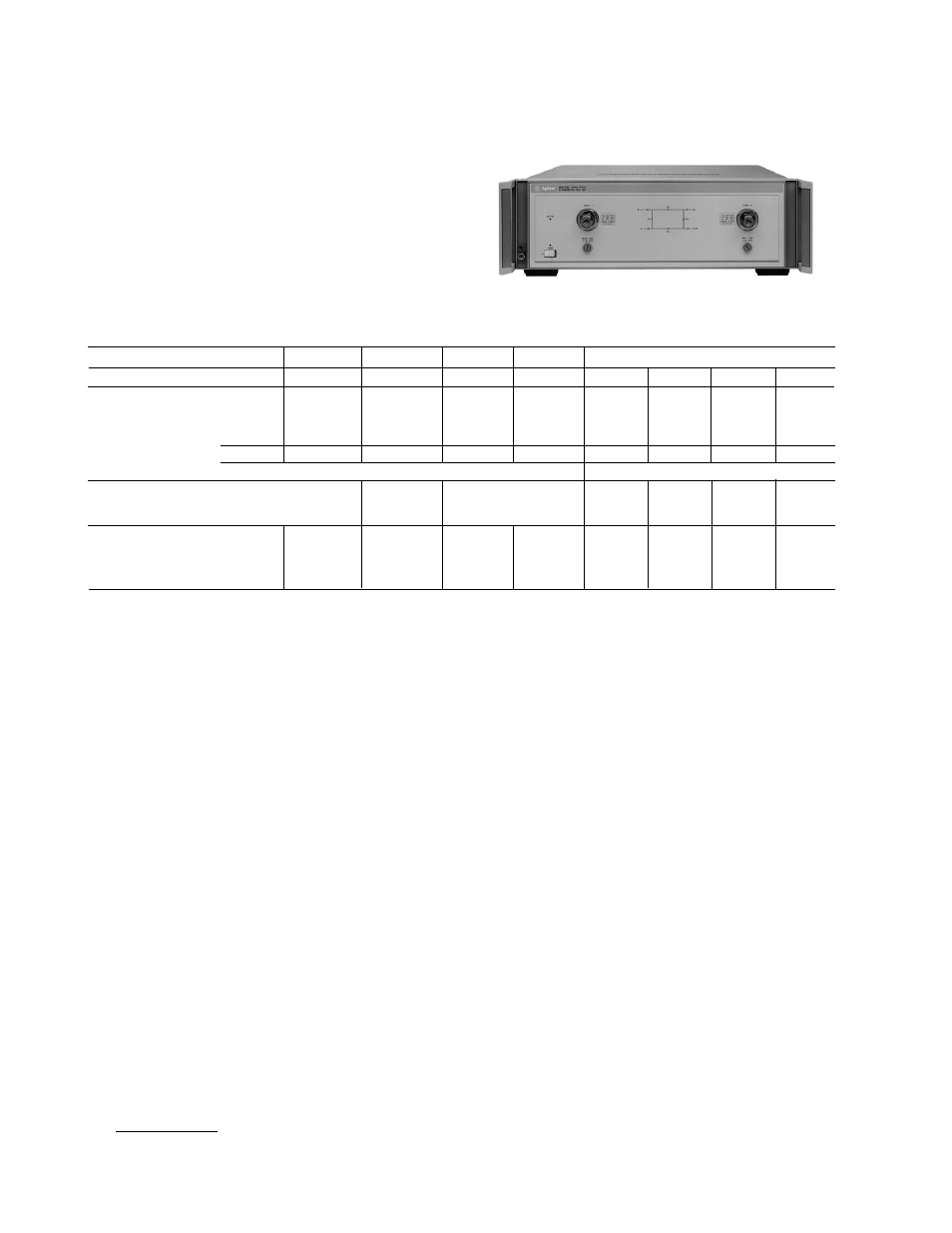
Combining the 8510C network analyzer with
an 8514B, 8515A, or 8517B results in a system for making
full S-parameter measurements. The dual port architec-
ture of the test sets develops a separate reference chan-
nel for each incident port. RF switching is done with a
single built-in electronic switch.
Test set general information
Various configurations are available for all test sets.
Please see the 8510 Network Analyzer
Configuration Guide.
8514B
8515A
8517B
85110A
85110L
85105A/85104A
Frequency range (GHz)
0.045 to 20
0.045 to 26.5
0.045 to 50
2 to 20
0.045 to 2
33 to 50
40 to 60
50 to 75
75 to 110
Test ports (port 1 or 2)
Nominal operating
power level (dBm)
2 to –6
–5 to –25
+2 to –29
0 to –3
0
0
0
0
–3
+5 to –16
1
Connector type
3.5 mm (m)
3.5 mm (m)
2.4 mm (m)
3.5 mm (m)
7 mm
WR-22
WR-19
WR-15
WR-10
Impedance, DC bias
50
Ω nominal, 500 mA, 40 Vdc maximum
Waveguide impedance, no bias
Attenuation range
(incident signal)
0 to 90 dB, in 10 dB steps
0 to 60 dB, in
0 to 90 dB, in 10 dB steps
N/A
N/A
N/A
N/A
10 dB steps
RF input connector
(rear panel)
Max. input power
+16 dBm
+14 dBm
+16 dBm
+14 dBm
+14 dBm
+13 dBm
+13 dBm
+13 dBm
+13 dBm
Connector type
3.5 mm (f)
3.5 mm (f)
2.4 mm (f)
3.5 mm (f)
3.5 mm (f)
3.5 mm (f)
3.5 mm (f)
3.5 mm (f)
3.5 mm (f)
1.
8517B Option 007