System capabilities – Atec Agilent-8510C User Manual
Page 15
15
Measurement
Number of display channels: Two display channels are
available.
Number of display parameters: The four basic param-
eters, S11, S21, S12, S22, can be displayed for either
selected channel in either a “four quadrant” or an “over-
lay” format.
Measurement parameters: S11, S21, S12, S22.
Parameters may be redefined by the user for special
applications. Conversion to Z1 (input impedance), Z2
(output impedance), Y1 (input admittance), Y2 (output
admittance), and 1/S is also provided.
Domains available: Frequency, time (Option 010), pulse
profile
2
(Option 008), auxiliary voltage (rear panel output
acting as device stimulus, range is ±10 VDC), and power
3
(sweep power level at a CW frequency).
Formats
Cartesian: log/linear magnitude, phase, group delay,
SWR, real part of complex parameter, imaginary part of
complex parameter.
Smith chart: Marker format can be selected as log magni-
tude, linear magnitude, R + jX, or G + jB.
Polar: Marker format can be selected as log magnitude,
linear magnitude, phase, or real and imaginary.
Data markers: Five independent data markers read out
and display the value of the formatted parameter and
stimulus (frequency, time, or auxiliary voltage).
Marker functions
Marker search: Specific trace values can be located, such
as MAX, MIN, and target (for example–3.00 dB point)
Discrete/continuous: Markers can indicate data at actual
data points or they can interpolate between data points to
allow the setting of a marker at an exact stimulus value.
Delta marker: Marker readout shows difference between
active marker and the reference marker (any marker can
be used as the reference).
Group delay characteristics
Group delay is computed by measuring the phase change
within a specified step (determined by the frequency
span and the number of points per sweep).
Aperture: Determined by the frequency span, the num-
ber of steps per sweep, and the amount of smoothing
applied.
Minimum aperture = (frequency span)/(# points –1)
Maximum aperture = 20% of the frequency span
Range: The maximum delay is limited to measuring
no more than ±180 degrees of phase change within the
minimum aperture.
Range = 1/(2 x minimum aperture)
For example, with a minimum aperture of 200 kHz,
the maximum delay that can be measured is 2.5 µsec.
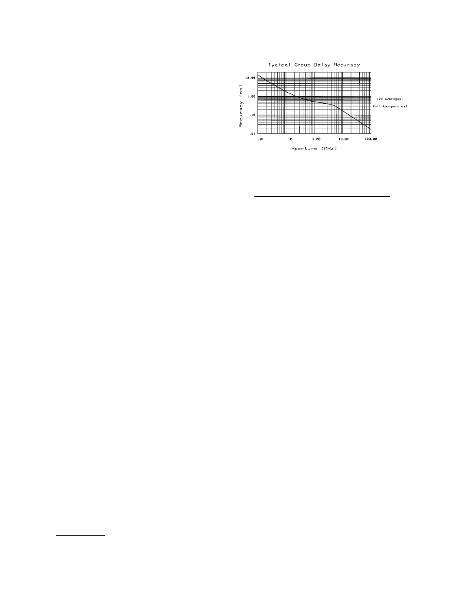
Accuracy: The following graph shows group delay accu-
racy at 20 GHz with an 8514B test set and an
83621A operating in stepped sweep mode. Insertion loss
is assumed to be zero.
In general, the following formula can be used to deter-
mine the accuracy, in seconds, of a specific group delay
measurement.
0.003 x Phase accuracy (deg) + delay (sec) x linearity (Hz)
Aperture (Hz)
Depending on the aperture and the device length, the
phase accuracy used is either incremental phase accuracy
or worst case phase accuracy. The above graph shows this
transition.
Source control
All source control is provided from the 8510C front panel.
Compatible sources
8360 series synthesized sweeper
8340A/B synthesized sweeper
4
8341A/B synthesized sweeper
4
8350B sweep oscillator with 835xx RF plug-in
4
(ramp sweep mode only)
Sweep limits: Set start/stop or center/span of the stimulus
parameter (frequency, time, or auxiliary voltage).
Measured # points per sweep: Selectable as 51, 101,
201, 401, or 801 points. In frequency list mode, the
number of points can range from 1 to 792.
Sweep modes
Ramp sweep
5
(analog)
Stepped sweep (available with all sources except the
Agilent 8350B): A faster version of step sweep, called “quick
step”, is selectable when using an 8360 series synthesized
sweeper.
Frequency list sweep: Define up to 30 different arbitrary
sub-sweep frequency ranges by specifying start/stop,
center/span, or CW sweeps. Define the number of points
or step size for each range. Display all segments or a
single segment on-screen. All frequencies are synthesized
if using the 8340/41 or 8360 series synthesized sweepers.
Frequency domain only.
Single point (single frequency)
Fast CW mode (GPIB only): Raw data (real and imagi-
nary) is sent immediately to GPIB as soon as it is taken.
Display is blanked in this mode. The source is phase-
locked once when entering this mode, but is not re-phase-
locked at each point. Must be triggered externally (TTL).
Data is available approximately 500 µsec after the trigger
pulse is received.
1.
The symbol ‘denotes a new feature or capability due to the 8510C firmware revision 7.0.
2.
Pulse profile domain is not available in the 8510XF systems.
3.
Power domain requires 8360 series sources. Sources with firmware revisions prior to 01 Oct 93 require updating.
4.
The 8340, 8341 and 8350 series sources are not compatible with the 8510XF systems.
5.
Ramp sweep mode is not available in the 8510XF systems.
System capabilities
1