Alpha Technologies Cordex Controller Ver.2.0 User Manual
Page 50
Refer to the back of this manual for Factory Service and Technical Support contact information
Alpha Technologies Ltd.
034-136-C0 Rev B WC
Printed in Canada. © 2010 Alpha Technologies Ltd. ALPHA and CORDEX are trademarks of Alpha Technologies Ltd. All Rights Reserved.
Page 48 of 122
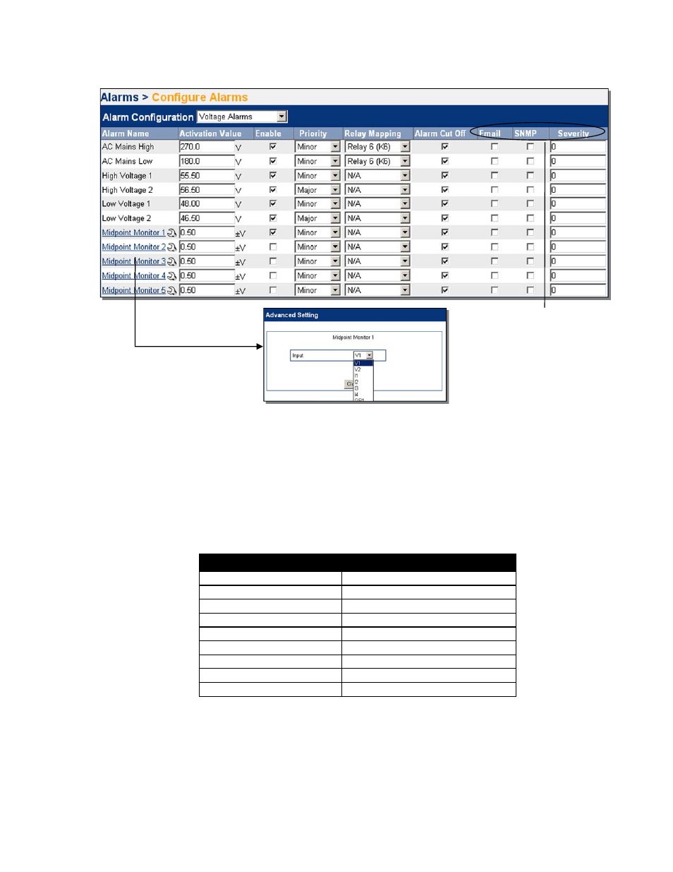
The web interface provides a list of all alarms in one place. The configuration of most alarms may be done on this
one screen:
Figure 39–Configure Alarms sample web interface window
6.5.3.1
Overview of Output Relay Channels and Configuration
One active control can be mapped for each of the relays; for example, Relay 1 can be
unassigned from LVD 1 then remapped as an alarm relay.
Any alarm (even multiple alarms) can be mapped to any unoccupied relay.
The table below summarizes the output channel assignments:
Channel Description
Factory Default Designation
Relay 1
LVD 1
Relay 2
LVD 2
Relay 3
LVD 3
Relay 4
POWER SYSTEM MINOR ALARM
Relay 5
POWER SYSTEM MAJOR ALARM
Relay 6
AC MAINS HIGH/LOW ALARM
Relay 7
RELAY 7 (Unassigned)
Relay 8
RELAY 8 (Unassigned)
Relay 9 – 16
…(Unassigned)
Table A–Output channel assignments
The Alarms that have an
extra (advanced) setting
will appear as a link.
Click on the link to open a
new window for editing
the advanced setting.
Supervisor may toggle the
check box to select e-mail
notification. See 10.3.3.
When selecting SNMP, the
severity level (numeric) may
also be set.