5 analog signals display (active area) – Alpha Technologies Cordex Controller Ver.2.0 User Manual
Page 24
Refer to the back of this manual for Factory Service and Technical Support contact information
Alpha Technologies Ltd.
034-136-C0 Rev B WC
Printed in Canada. © 2010 Alpha Technologies Ltd. ALPHA and CORDEX are trademarks of Alpha Technologies Ltd. All Rights Reserved.
Page 22 of 122
4.5
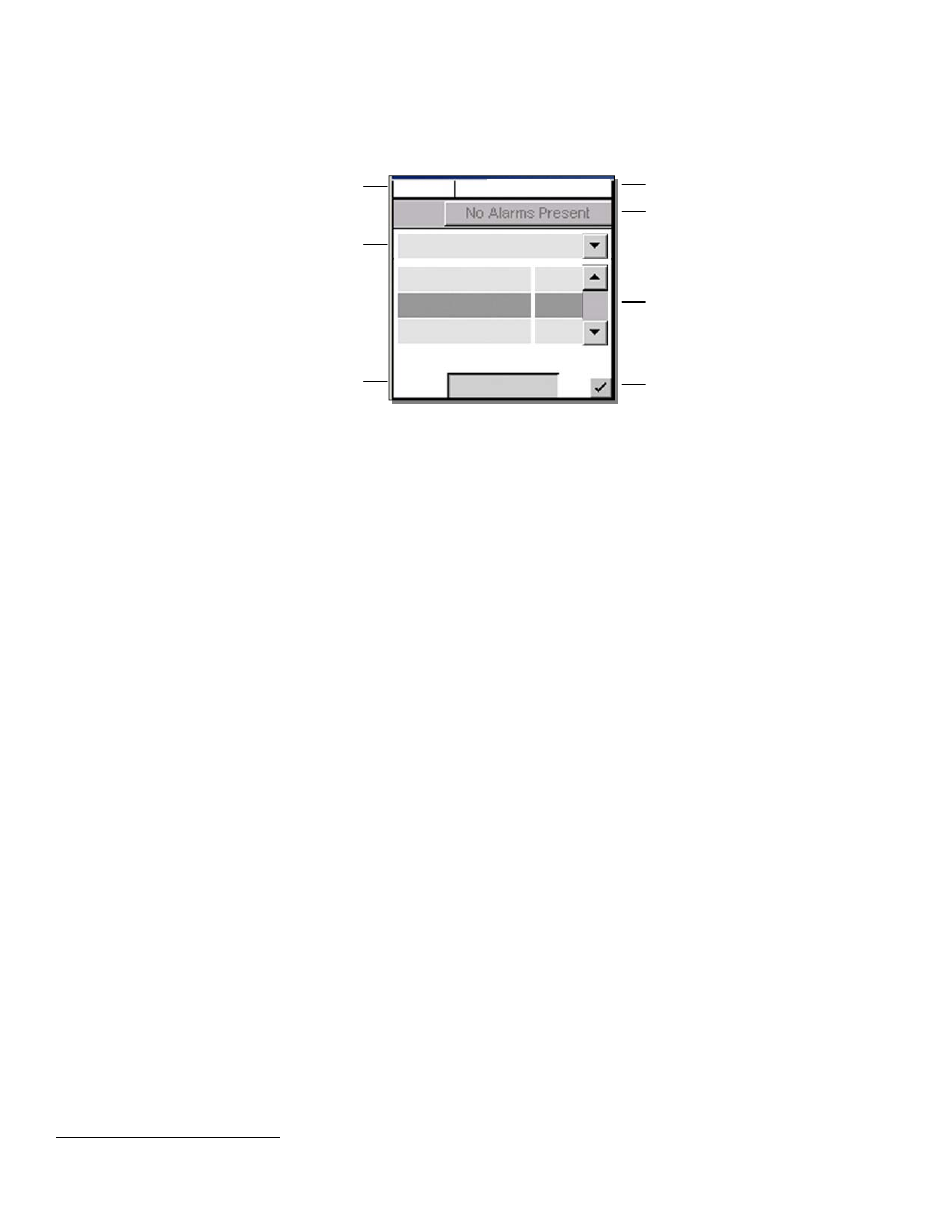
Analog Signals Display (active area)
Tap this active area
3
, top right of the “home” page (Figure 2), to enter a new window of operation for analog
signals display and configuration, see Figure 10 below:
Figure 10–Analog signals display screen
The item selected from the analog signals active area will now be the highlighted item listed in the new window.
The pull-down menu enables the user to select the signal group; signal items are listed below the group heading.
Navigate the menu list to select the desired item.
4.5.1
Controller Signals
Once a menu item is selected, tap the “Configure” button to produce another window and list of items to navigate,
see 6.6.2. To edit items, the User will be prompted for a password (via a pop-up window).
4.5.2
Analog Inputs
Once a menu item is selected, tap the “Calibrate” button to produce another window and list of items to navigate,
see 6.6.1. To edit items, the User will be prompted for a password (via a pop-up window).
4.5.3
Digital Inputs
Under this menu heading, the user can view the list of digital inputs, see Table B.
4.5.4
Rectifier Signals
Under this menu heading, the user can view the list of rectifier signals, see Table E.
4.5.5
Custom Signals
Once a menu item is selected, tap the “Configure” button to produce another window and list of items to navigate.
To edit items, the User will be prompted for a password (via a pop-up window).
4.5.6
Converter Signals
Under this menu heading, the user can view the list of converter signals, see Table H.
4.5.7
Counter
Once a menu item is selected, tap the “Configure” button to produce another window and list of items to navigate.
To edit items, the user will be prompted for a password (via a pop-up window).
4.5.8
Timers
Once a menu item is selected, tap the “Configure” button to produce another window and list of items to navigate.
To edit items, the user will be prompted for a password (via a pop-up window).
4.5.9
ADIO Signals
Under this menu heading, the user can view the live data from an ADIO device (i.e., Cordex Smart Peripherals)
connected to the CXC. Refer also to Section 6.6.2.6, Example Four.
3
When labels are not shown, digits are displayed two rows high. See Figure 2 for Normal Operation. Tap to minimize (see Figure 1) and tap again to
enter new window of operation.
Mode (+Temp Comp) display
Pull-down menu (heading) also includes:
Analog Inputs, Digital Inputs,
Rectifier Signals, Custom Signals,
Converter Signals, Counter,
Timers, ADIO Signals
Change heading to access
menu item desired
Accept changes and
return to previous screen
Battery Volts and
Load Current display
FL + TC
54.00V 250A
Alarm Indication
Controller Signals
Load
Current 250
Battery Voltage
54.00
Battery Current
5.4
Configure
Sliders and scroll bars
are used for navigation
Select menu item to configure
Tap to edit selected menu item
User will be prompted for password