Tank tilt / offset calculations, Figure 9: probe module wiring – Franklin Fueling Systems TSP-LL2 User Manual
Page 7
7
Probe
Module
RUN
ERR
9
8
7
–Blk
+Red
–Blk
+Red
–Blk
+Red
12
11
10
–Blk
+Red
–Blk
+Red
–Blk
+Red
3
2
1
–Blk
+Red
–Blk
+Red
–Blk
+Red
6
5
4
–Blk
+Red
–Blk
+Red
–Blk
+Red
Probe
SHLD
- (BLK)
+ (RED)
SHLD
- (BLK)
+ (RED)
Non-Hazardous
Location
Hazardous Location
Class I, Division 1, Group
D, Group IIA, Zone 0
Figure 9: Probe Module Wiring
Refer to manual 000-2142, Fuel Management System
Programming guide and 000-2150 Fuel Management
System Installation guide for information about setting up
the probe with the tank gauge.
For Colibri Tank Gauge Consoles, refer to manual
000-2153, Colibri Automatic tank Gauge Installation Guide,
and 000-2155, Colibri Set-Up and Operation Guide. For
Colibri manuals on the web, go to:
www.franklinfueling.com/colibri/literature.aspx
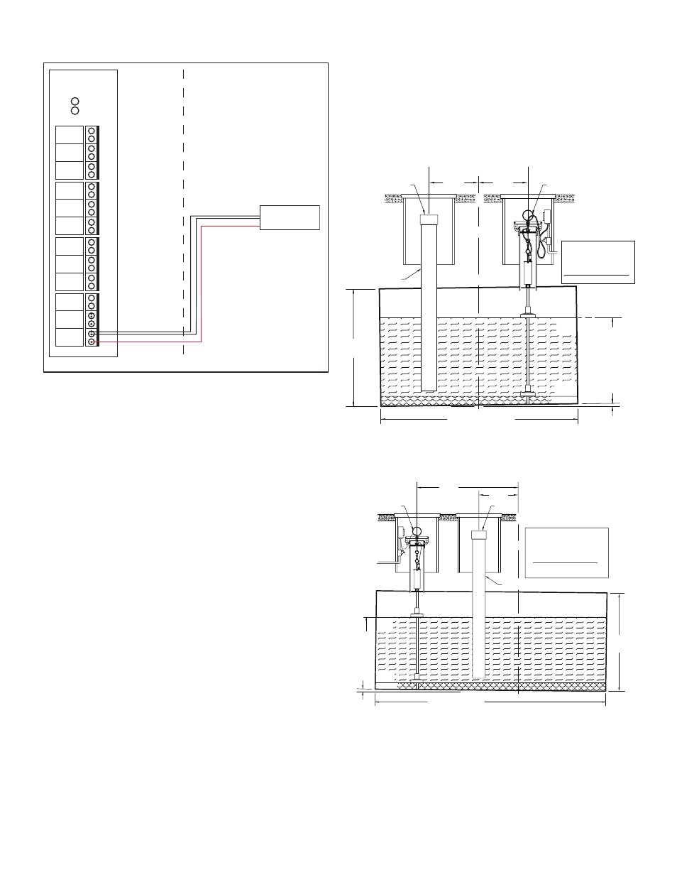
Tank Tilt / Offset Calculations
If the data to calculate tank tilt is not known, or if the tank is
not seriously tilted, then use +/– offsets to adjust the probe
readings to match the stick readings at fill.
Figure 10 shows the tank tilt formula to use when the fill
tube and probe are on opposite sides of the tank center-
line. Figure 11 shows the formula to use when the fill tube
and probe are on the same side of the tank center-line.
Tank shown
tilted
LENGTH OF TANK
TANK
DIAMETER
L
C
PRODUCT
LEVEL
CL
WATER
" XF "
" XP "
CENTER OF TANK
Fill
level
Probe
TOP OF TANK
" LF "
Level
at Fill
DROP TUBE
" LP "
Level
at Probe
FUEL
FUEL
Fill & Probe on
opposite sides of
Tank
Center...
Product / Water
Offset =
XP + XF
(LF - LP) * XP
AIR
Figure 10: Tank Tilt Calculation
Probe and Fill on Opposite Sides
WATER
Fill
" XP "
" XF "
AIR
FUEL
FUEL
Fill & Probe on
the same side of
the tank
Product / Water
Offset =
CENTER OF TANK
level
Probe
" LP "
Level
at Probe
" LF "
Level
at Fill
(LF - LP) * XP
XP - XF
DROP TUBE
TOP OF TANK
LENGTH OF TANK
Product
Level
Tank
shown
tilted
LC
Tank
Diameter
Figure 11: Tank Tilt Calculation
Probe and Fill on Same Side