Franklin Fueling Systems TSP-LL2 User Manual
Page 4
4
Suspended Probe Installation
This procedure must be done with leak detection probes
and is optional for inventory probes. Before starting the
probe installation, be sure that you have the necessary
hardware:
• Level probe(s)
• Product and water floats,
• Probe installation kit.
For each tank, locate the following:
• LL2 level probe
• Product float
• Water float-optional, is identified by color:
(Blue – Diesel, Red – Gasoline)
• Threaded adjustment eye bolt and suspension chain
(with wing nut and split ring attached)*
• Steel support plate (with rubber grommet and insulating
washer installed)*
• Four Inch NPT riser adaptor*
• Riser cap*
• Compression gland seal fitting (cord grip)*
• (3) Moisture resistant, no strip, electrical wire splice
connector*
* Included in the TS-K4A probe installation kit.
Installation
1. Measure from the top of the riser pipe to the
bottom of the tank-record value in inches.
2. Measure the overall length of Probe.
3. Subtract the probe length from the distance
measured from the top of the riser pipe to the
bottom of the tank, and then add 1/2 inch to this
distance. This value is the
TOTAL LENGTH OF
THE CHAIN INCLUDING THE SPLIT RING AND
ADJUSTMENT EYEBOLT.
4. The suspension chain must be cut to the exact
length required.
5. Remove the split ring from the end of the chain and
cut the chain to the correct length.
6. Reattach the split ring to its end and measure the
total overall length to make certain that it is within
one half inch of correct value.
Note; When using a 2" or 3" riser you will replace the
bottom spacer with the 3" spacer included in the
float kit. When using a 2" riser, cut back the spacer
at the marks. The 4" probes are installed with no
modification.
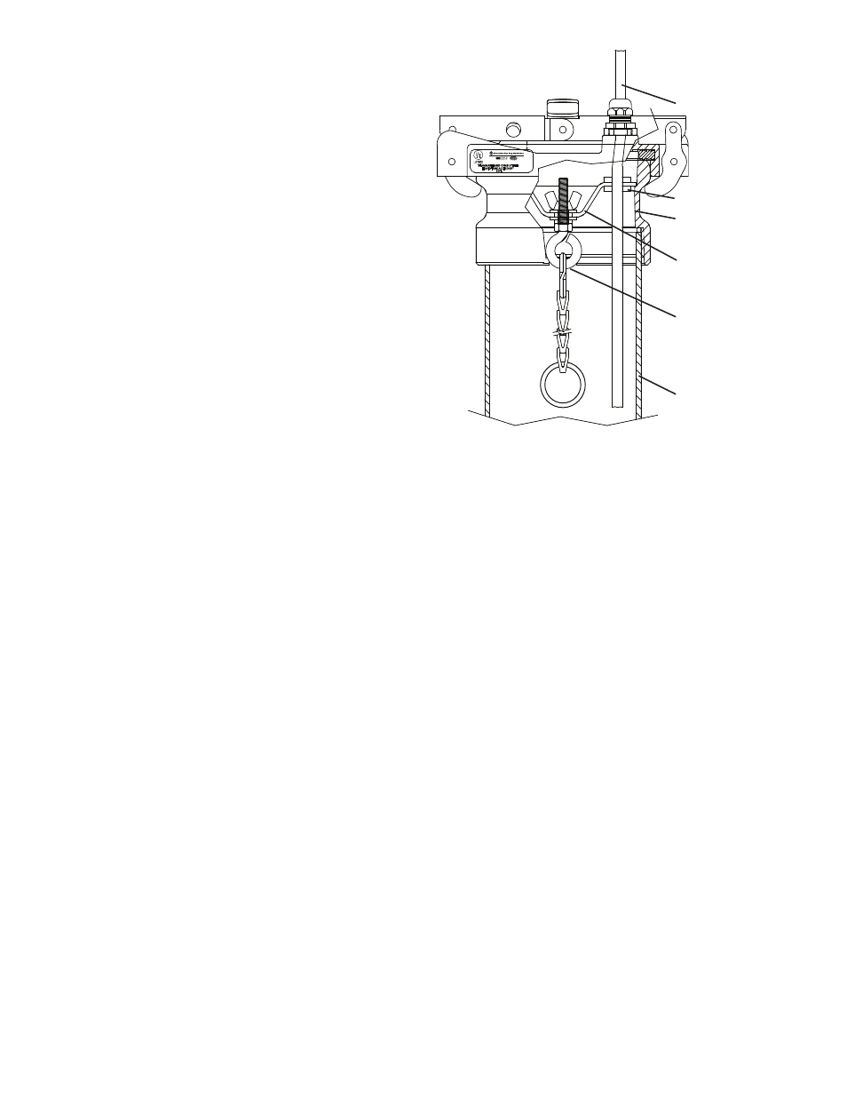
R
Riser Cap
Support Plate
Riser Pipe
Eyebolt
Probe Cable
Rubber Grommet
Figure 3: Installation of Suspended Probe
7. Apply pipe sealant to the male riser threads.
8. Screw the riser cap adapter into the top of the riser
pipe. Tighten to 20-25 ft-lbs.
9. Connect the probe to the split ring on the chain.
10. Carefully position the steel support plate
containing the rubber grommet and insulating
shoulder washer into the riser cap.
11. Guide the probe cable through the rubber
grommet.
12. Unscrew the adjusting eyebolt so the probe just
touches the bottom of the tank.
13. Turn the wing nut clockwise, 4 full turns (only).
This will raise the probe approximately ¼” above
the bottom of the tank.
14. Push the probe cable through the compression
fitting on the probe cap.
15. Install the probe cap on the riser cap adapter such
that the compression fitting is aligned with the
rubber grommet.
16. Tighten the compression fitting to make a
watertight seal.