Bottom-mount probe installation – Franklin Fueling Systems TSP-LL2 User Manual
Page 5
5
Adjusting the probe height (¼" off the bottom of tank)
Make sure the probe is sitting on the bottom of the tank
by loosening the wing nut until you feel slack in the chain
(the probe is resting on the bottom of the tank).Then turn
the wing nut clockwise until you feel that there is no slack
in the suspension chain. Hold the end of adjustment rod
and turn the wing nut clockwise, 4 full turns (only). This
will raise the probe approximately ¼ of an inch above the
bottom of the tank.
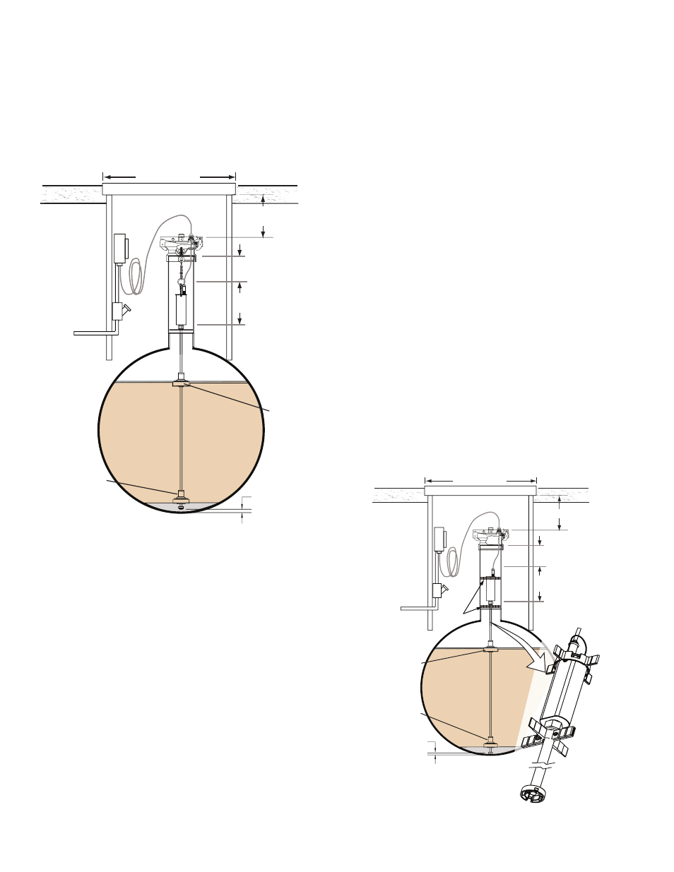
PRODUCT
Ullage
Install Probe
1/4" (6.4 mm) Above
Bottom of Tank
Water Float
Product Float
6.0" (152 mm) Minimum
18.0" (457 mm) Maximum
14" (356 mm) Minimum
Manhole Cover
8.0" (203 mm)
Reference
5"(127 mm)
Minimum
NTS
Figure 4: Suspended Probe Installed
Final Suspended Probe Installation Steps
1. Push the probe’s cable though the compression
gland fitting at the waterproof junction box. Make
sure that you leave enough cable from the level
probe to the junction box (tie-wrap a coiled service
loop) so that the probe can be easily removed and
reinstalled without rewiring and splicing.
2. Tighten the compression gland fitting at the
junction box so that it grips the cable tightly and
creates a watertight seal.
3. Position the lockable TSP-K4A probe cap on the
riser cap adapter such that the compression fitting is
aligned with the rubber grommet and snap it in place.
4. Tighten the riser cap compression fitting so that it
grips the cable tightly and forms a watertight seal
Note: When removing the probe, loosen the cable
compression fitting.
Bottom-Mount Probe Installation
The bottom-mount probe option is for inventory control
probes. Tank leak testing and density probes need to be
suspended from the riser cap.
The bottom-mount assembly consists of:
• Top spacer on the top of the probe head for 3" or 4" probes
• Bottom spacer below the probe head
• Probe foot mounts at the bottom of the probe shaft
The foot is ¼" thick so when installed the probe end will be
¼" off the bottom of the tank.
When using a 2" riser you will remove the top spacer and
replace the bottom spacer with the 2" spacer included in
the float kit. When using a 3" riser, cut back the top spacer
and replace the bottom spacer with one included in the
float kit. The 4" probes are installed with no modification.
This is solely for the I-probes, all leak detection and density
probes MUST BE Suspended.
Single Thermistor Probe
The probe will have one RTD near the bottom of the
probe shaft. The Net Volume will be based on the one
temperature reading vs. the average of the 5 RTDs in
current Inventory probes.
Note: The Inventory Probes MUST NOT be used for Leak
Detection.
A sticker on the head of the I-probe indicates that it is for
inventory use only. An extra sticker is provided to be kept
near the console for gradient programming. Installers must
be aware of the probe type in sites that have a mix of
inventory-specific and leak detection probes.
PRODUCT
Ullage
Probe end held
1/4" (6.4 mm) Above
Bottom of Tank
Water Float
Product
Float
6.0" (152 mm) Minimum
14" (356 mm) Minimum
Manhole Cover
8.0" (203 mm)
Reference
3" (76 mm)
Minimum
N.T.S.
Spacers
Figure 5: Bottom-Mount (I-Probe) Installed